

네오픽셀 LED 스트립용 NeoPXL8 피더윙 보드 -8개 DMA 출력
(Adafruit NeoPXL8 FeatherWing for Feather M4 - 8 x DMA NeoPixels!)
개요
- 본 제품은 8개의 DMA 출력을 지원하는 네오픽셀 LED 스트립용 NeoPXL8 피더윙 보드입니다.
- 네오픽셀 LED의 까다로운 timing 제어 문제를 해결하기 위해 ATSAMD51 MCU Timer 0 의 waveform 모드를 이용하여 DMA상에 8개의 유니크한 웨이브폼을 생성하여 네오픽셀 LED 제어를 할 수 있게 하여 줍니다.
- 이를 위한 NeoPXL8 Arduino library 와 본 보드가 나오게 되었씁니다.
- 라이브러리는 Feather M4 보드상에서 동작하며, 최대 8개 LED 스트립의 DMA 출력을 동시에 처리할 수 있습니다.
- 각 채널은 1750 RGB LED가 가능하여 총 8 x 1750 = 14000 픽셀 제어가 가능합니다.
특징
-
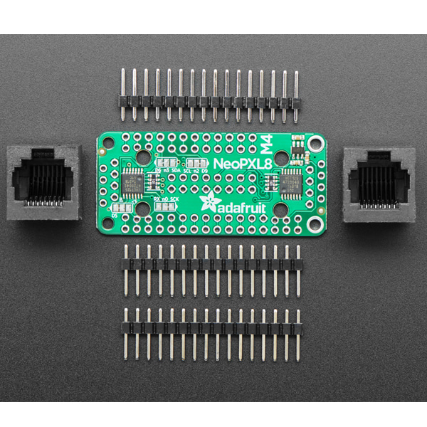
Dimensions (board only, no components): 51 x 22.8 x 2.6mm
Product Weight: 4.0g / 0.1oz
-
Thus were born the NeoPXL8 Arduino library and NeoPXL8 FeatherWing! The library runs on our Feather M4 and handles all the NeoPixeling for you, up to 8 strands of concurrent DMA output each one can be 1750 RGB pixels long for a total of 8 x 1750 = 14000 pixels. That leaves you some RAM for your code to run in as well. Even though you could connect that many pixels, what we think this 'Wing does best is take advantage of DMA + the SAMD51's blazingly-fast 120MHz processor to manage animations for hundreds of pixels with ease
If you have a SAMD21 Feather, check out the sister product - NeoPXL8 FeatherWing for M0 boards.
To make connection easy, this FeatherWing does the level-shifting and pin arrangements for you. All 8 strands have a level shifter that converts the 3.3V logic level to 5V logic, there's a little switch-cap converter that generates the clean 5V power supply for you. Then a 100 ohm resistor in line after the buffer reduces ringing on long wiring runs.
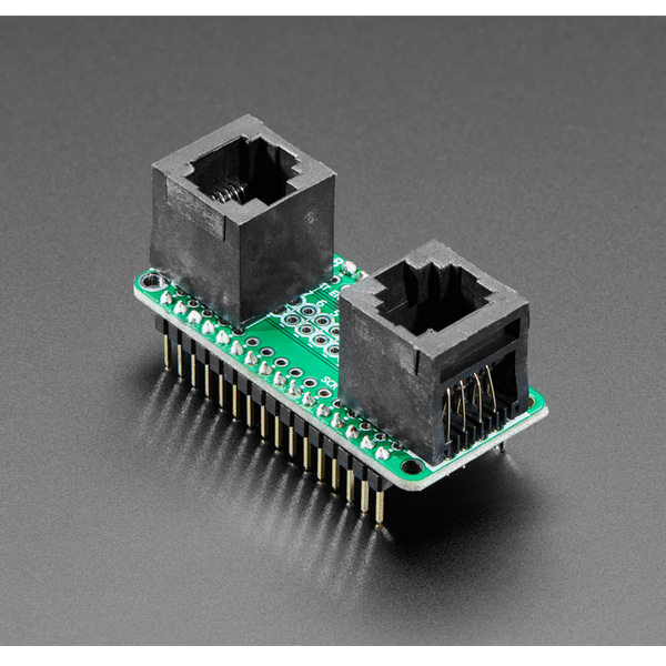
You get two options for connecting NeoPixels:
- 2 x 8 Header with ground and 5V-logic signal, in pairs
- 2 x RJ-45 'Ethernet' Jacks, with ground and 5V-logic signal per twisted pair. This matches the same wiring as the OctWS2811
To keep the 'Wing compact we let you choose which wiring you'd like to go with, just solder in the connectors you prefer. Then you'll also need to provide power to the NeoPixels. Since you'll need many Amps of current, we don't manage that through the Wing - the PCB copper would be too limiting. We recommend using terminal blocks or bus bars to connect all the ground/5V power wires together and powering them from their own chunky 5V supply.
Since we are using TCC0 (Timer 0), we are limited in what pins can be used for NeoPixel output. Here are the options you have:
- Output #0 comes from either SPI SCK or RX (selectable)
- Output #1 comes from either D5 or TX (selectable)
- Output #2 comes from either D9 or I2C SCL (selectable)
- Output #3 comes from either D6 or I2C SDA (selectable)
- Output #4 comes from Digital #13
- Output #5 comes from Digital #12
- Output #6 comes from Digital #11
- Output #7 comes from Digital #10
As you can see, some of these pins are fixed (D10, 11, 12 and 13) and the rest have two options. If you absolutely cannot spare both options, you can disable that from the NeoPXL8 DMA output and live with 7 strands only.
While we designed this specifically for use with Feather M4 (SAMD51 based), you could use it with other Feathers, for the level shifting capabilites. You'll just have to figure out what NeoPixel driver firmware you can use and what pins are available.

