MAX31334 RTC 모듈 -I2C
(RTC 19 CLICK)
개요
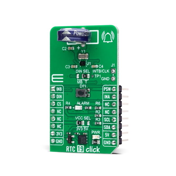
- 본 제품은 MAX31334 RTC 모듈 -I2C 입니다.
- MAX31334 칩을 기반으로 디자인된 제품으로 I2C 인터페이스를 가지고 있습니다.
- 인터럽트 신호로 출력을 내보내는 알람 기능을 가지고 있습니다.
- 솔더 점퍼에 따라 3.3V/5V 시스템과 사용이 가능합니다.
특징
-
RTC 19 Click is based on the MAX31334, an ultra-low power, real-time clock (RTC) time-keeping device from Analog Devices. The MAX31334 is configured to transmit calendar and time data to the MCU (24-hour/12-hour format) based on a 32.768kHz quartz crystal and comes with an integrated interrupt generation function. It reads and writes clock/calendar data from and to the MCU in units ranging from seconds to the last two digits of the calendar year, providing seconds, minutes, hours, days, months, year, and date information. The end-of-the-month date is automatically adjusted for months with fewer than 31 days, including corrections for the leap year.
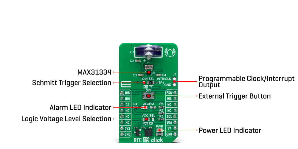
The MAX31334 features an integrated high-side power pass switch (detectable through a PSW pin and drawn to the TP1 testpoint for external use), enabling idle, ultra-low power modes on duty-cycled applications by disconnecting power to other devices on the system. The power switch ON/OFF durations can be controlled by periodic interrupt sources such as a countdown timer (programmable from 100ms to 1hr), alarms (1s resolution), or by an external interrupt from a DIN pushbutton.
The DIN signal represents a digital Schmitt trigger that records timestamps or asserts an interrupt on its falling/rising edge. In addition to the DIN button, the state of this signal can also be changed digitally using the DIN pin, routed on the RST pin of the mikroBUS™ socket. The selection can be performed using an onboard SMD jumper labeled DIN SEL, placing it in an appropriate position marked as MB or T, where MB stands for mikroBUS and T for the button.
This Click board™ communicates with MCU using the standard I2C 2-Wire interface to read data and configure settings, supporting a Fast Mode operation up to 400kHz. It also incorporates an alarm circuitry configured to generate a time-of-day/date interrupt signal. An alarm (interrupt) signal, marked as INA and routed to the INT pin of the mikroBUS™ socket, allows outputting warning every day or on a specific day visually indicated by a red LED marked as ALARM.
By utilizing an automatic backup switch, when the main supply drops below the programmed threshold voltage, this RTC can use an external power source (220mF supercapacitor), allowing uninterrupted operation. Besides an automatic backup switchover circuit, this board also carries a header for additional alarm/interrupt and a programmable clock output signal for frequencies from 1Hz to 32kHz available on an onboard J1 header. In addition, this signal also exists on the AN pin of the mikroBUS™ socket marked with INTB.
This Click board™ can operate with both 3.3V and 5V logic voltage levels selected via the VCC SEL jumper. This way, it is allowed for both 3.3V and 5V capable MCUs to use the communication lines properly. However, the Click board™ comes equipped with a library containing easy-to-use functions and an example code that can be used, as a reference, for further development.
SPECIFICATIONS
Type RTC Applications Can be used for general-consumer applications, including daily alarms, metering applications, and others requiring an accurate RTC for their operation On-board modules MAX31334 - real-time clock from Analog Devices Key Features Low power consumption, automatic backup supply switch, integrated power switch, high accuracy, clock/calendar feature, programmable interrupt and clock output, automatic leap year recognition, and more Interface I2C Compatibility mikroBUS Click board size M (42.9 x 25.4 mm) Input Voltage 3.3V or 5V
문서
연관제품
- 연관제품 1