Functional Description:
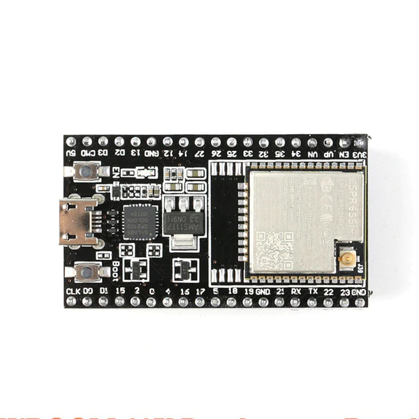
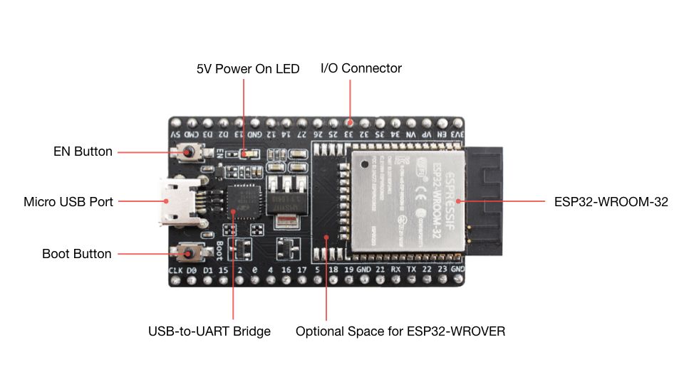
The following list and figure below describe key components, interfaces and controls of ESP32-DevKitC V4 board.
ESP32-WROOM-32D
ESP32-WROOM-32D soldered to the ESP32-DevKitC V4 board.
Optional Space for ESP32-WROVER
Longer ESP32-WROVER modules may be soldered instead of the ESP32-WROOM-32.
USB-to-UART Bridge
A single chip USB-to-UART bridge provides up to 3 Mbps transfers rates.
Boot Button
Download button: holding down the Boot button and pressing the EN button initiates the firmware download mode. Then user can download firmware through the serial port.
EN Button
Reset button: pressing this button resets the system.
Micro USB Port
USB interface. It functions as the power supply for the board and the communication interface between PC and the ESP module.
Power On LED
Turns on when the power supply is applied to the board. For details see schematic in Related Documents.
I/O Connector
Most of the pins on the ESP module are broken out to the female pin headers on the board. Users can program ESP32 to enable multiple functions such as PWM, ADC, DAC, I2C, I2S, SPI, etc.
Note:
Some of broken out pins are used internally by the ESP32-WROOM-32, ESP32-WROOM-32D/U and ESP32-SOLO-1 modules to communicate with SPI memory. They are grouped on one side of the board besides the USB connector and labeled CLK, D0, D1, D2, D3 and CMD (GPIO6 - GPIO11). In general these pins should be left unconnected, otherwise access to the SPI flash memory / SPI RAM may be disturbed.
Power Supply Options:
There following options are available to provide power supply to this board:
Micro USB port, this is default power supply connection
5V / GND header pins
3V3 / GND header pins
Warning:
Above options are mutually exclusive, i.e. the power supply may be provided using only one of the above options. Attempt to power the board using more than one connection at a time may damage the board and/or the power supply source.
Note on C15:
The C15, on the board of earlier batches of V4, may bring two issues:
1. The board may boot into download mode;
2. If users output clock on GPIO0, C15 may impact the clock output.
As a result, if users believe that C15 will impact their use of the board, they can remove it completely (please refer to the screenshot below for the precise location of C15 that is colored in yellow). Otherwise, users do not need to concern about C15.