아날로그 전압 - PWM 변환 모듈 -LTC6992CS6
(AN TO PWM 2 CLICK)
개요
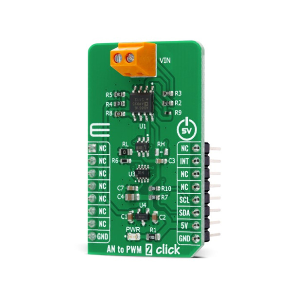
- 본 제품은 아날로그 전압 - PWM 변환 모듈 -LTC6992CS6입니다.
- 아날로그 전압 신호를 입력 받아 고정된 주파수의 PWM 전압 출력으로 변환하여 주는 제품입니다.
- duty cycle은 입력 전압에 비례하여 변화됩니다.
- LTC6992CS6 실리콘 오실레이터를 기반으로 디자인된 제품입니다.
- -2.5V ~ 2.5V 아날로그 입력 전압 범위와 최대 1Mhz 주파수 범위를 가진 제품입니다.(frequency error less than 1.7%)
- 5V 시스템과 사용이 가능합니다.
특징
-
Type ADC Applications Can be used for heater control, PWM servo loops, LED dimming, signal isolation, and other duty cycle control applications. On-board modules AN to PWM 2 Click is based on the LTC6992CS6, a voltage-controlled PWM generator from Analog Devices. Key Features Low power consumption, good temperature stability, wide frequency range, low frequency error, and more. Interface I2C Compatibility mikroBUS Click board size M (42.9 x 25.4 mm) Input Voltage 5V
문서
-
HOW DOES IT WORK?
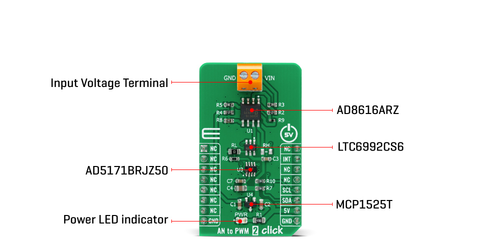
AN to PWM 2 Click is based on the LTC6992CS6, a voltage-controlled PWM generator from Analog Devices. This device is chosen because it keeps its output clocking at all times, and it offers glitch-free, a first cycle-accurate startup within 500μs of Power-On. The output of the this Click board™ can source or sink up to 16 mA, and it has a linear response, so applying a voltage in a range of -2.5 to 2.5V on its input, will result in generating the PWM pulse train with duty cycle linearly proportional to the input voltage. The output PWM signal is brought to the INT pin of the mikroBUS™ socket to enable fast and precise duty cycle measurement using the interrupt routines.
The LTC6992CS6 has a MOD pin which represents pulse-width modulation input where is necessary to bring an analog signal. To bring the corresponding signal to that pin, this Click board™ uses an analog circuitry made of OpAmp AD8616ARZ from Analog Devices. In the first part of the circuit, amplifier OPA1 attends to adjust the input signal through a reference voltage of 2.5V by the MCP1525 from Microchip and applied input voltage in a range of -2.5 to 2.5V. The next part of the circuit is the voltage divider and amplifier OPA2 which has the function of a buffer, after which the signal required by the MOD pin of the LTC6992CS6 is obtained.
The output frequency can range up from 3.81Hz to 1MHz and is controlled via the AD5171, a 64-position (OTP) digital potentiometer from Analog Devices, which programs the LTC6992CS6’s internal master oscillator frequency. The output frequency is determined by this master oscillator and an internal frequency divider programmable to eight settings from 1 to 16384. It communicates with MCU using the standard I2C serial interface that operates at clock rates up to 400 kHz and represents the most accurate way to set the frequency. It’s also left the possibility to adjust the frequency via resistors RH and RL by placing resistors of appropriate resistance.
This Click Board™ is designed to be operated only with a 5V logic level. A proper logic voltage level conversion should be performed before the AN to PWM 2 Click is used with MCUs with different logic levels. More information about the LTC6992CS6’s functionality, electrical specifications, and typical performance can be found in the attached datasheet. However, the Click board™ comes equipped with a library that contains easy-to-use functions, and a usage example that can be used as a reference for the development.
연관제품
- 연관제품 1