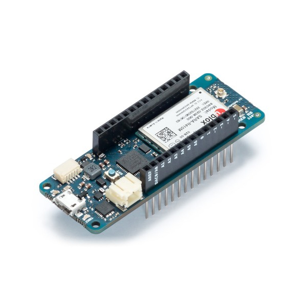
정품 아두이노 MKR NB 1500 쉴드 -LTE 통신
(ARDUINO MKR NB 1500)
개요
- 본 제품은 아두이노 MKR NB 1500 LTE 통신 쉴드입니다.
- ublox사의 SARA-R410M-02B LTE 모듈을 장착하고 있으며, Narrow Band IoT NB 및 LTE CAT M1 네트워크를 지원합니다.
- Cat M1/NB1 deployed bands 2, 3, 4, 5, 8, 12, 13, 20, 28 을 지원하여 글로벌하게 사용될 수 있도록 디자인되었습니다.
- 알림: 국내 통신사 사용여부는 각 통신사에 문의를 하여 주셔야 합니다.
특징
-
Microcontroller SAMD21 Cortex-M0+ 32bit Low Power ARM MCU Circuit Operating Voltage 3.3 V Security ECC 508 crypto chip ( datasheet ) I2S
1 Wireless radio
UBLOX SARA-R410M-02B ( documentation) ( Datasheet ) I2C
1 UART 1 SPI 1 Pinout (Digital, PWM, Analog) 22 I/O Digital (12 PWM),
7 Analog InputCompatibility MKR
문서
-
OSH: Schematics
The MKR NB 1500 is open-source hardware! You can build your own board using the following files:
EAGLE FILES IN .ZIPSCHEMATICS IN .PDF
Li-Po batteries, Pins and board LEDs
Antenna
The MKR NB 1500 has to be used with an antenna that can be attached to the board with the micro UFL connector. Please check that it can accept frequencies in the Narrow Band or CAT M1. Please note: for best result, do not attach the antenna to a metallic surface like car chassis, etc.
Battery capacity
Li-Po batteries are charged up to 4,2V with a current that is usually half of the nominal capacity (C/2). We use a specialized chip that has a preset charging current of 350mAh. This means that the MINIMUM capacity of the Li-Po battery should be 700 mAh. Smaller cells will be damaged by this current and may overheat, develop internal gasses and explode, setting on fire the surroundings. We strongly recommend that you select a Li-Po battery of at least 700mAh capacity. A bigger cell will take more time to charge, but won't be harmed or overheated. The chip is programmed with 4 hours of charging time, then it goes into automatic sleep mode. This will limit the amount of charge to max 1400 mAh per charging round.
Battery connector
If you want to connect a battery to your board be sure to search one with female 2 pin JST PHR2 Type connector.Polarity : looking at the board connector pins, polarity is Left = Positive, Right = GNDDownload here the Connector datasheet. On the board, connector is a Male 2pin JST PH Type.
VinThis pin can be used to power the board with a regulated 5V source. If the power is fed through this pin, the USB power source is disconnected. This is the only way you can supply 5v (range is 5V to maximum 6V) to the board not using USB. This pin is an INPUT.
5VThis pin outputs 5V from the the board when powered from the USB connector or from the VIN pin of the board. It is unregulated and the voltage is taken directly from the inputs. When powered from battery it supplies around 3.7 V. As an OUTPUT, it should not be used as an input pin to power the board.
VCC
This pin outputs 3.3V through the on-board voltage regulator. This voltage is the same regardless the power source used (USB, Vin and Battery).
LED ON
This LED is connected to the 5V input from either USB or VIN. It is not connected to the battery power. This means that it lits up when power is from USB or VIN, but stays off when the board is running on battery power. This maximizes the usage of the energy stored in the battery. It is therefore normal to have the board properly running on battery power without the LED ON being lit.
CHARGE LED
The CHARGE LED on the board is driven by the charger chip that monitors the current drawn by the Li-Po battery while charging. Usually it will lit up when the board gets 5V from VIN or USB and the chip starts charging the Li-Po battery connected to the JST connector.There are several occasions where this LED will start to blink at a frequency of about 2Hz. This flashing is caused by the following conditions maintained for a long time (from 20 to 70 minutes):- No battery is connected to JST connector.- Overdischarged/damaged battery is connected. It can't be recharged.- A fully charged battery is put through another unnecessary charging cycle. This is done disconnecting and reconnecting either VIN or the battery itself while VIN is connected.
Onboard LED
The onboard LED is connected to D6 and not D13 as on the other boards. Blink example or other sketches that uses pin 13 for onboard LED may need to be changed to work properly.
(*) Note : DO NOT CONNECT to the male JST connector present on the board anything else than a Li-Po battery whose characteristics are compliant with those indicated above. Please DO NOT POWER VIN with more than 5V.
Additional I2C Port
The MKR NB 1500 has an additional connector meant as an extension of the I2C bus. It's a small form factor 5-pin connector with 1.0mm pitch. The mechanical details of the connector can be found in the connector datasheet. The I2C port in addition to the SDA and SCL signals includes the GND and +5V power rails and a digital pin that might be useful when designing an expansion. The pinout is shown in the following image:

The connector we suggest for this additional I2C Port is the SHR-05V-S-B, also in the picture.