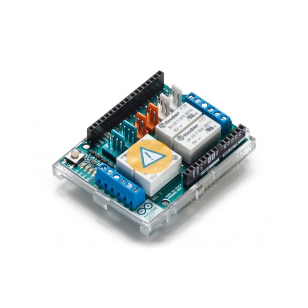
정품 아두이노 4채널 릴레이 쉴드
(ARDUINO 4 RELAYS SHIELD)
개요
- 본 제품은 정품 아두이노 4채널 릴레이 쉴드입니다.
- 네개의 LED는 각각의 릴레이의 on/off 상태를 표시합니다.
특징
-
Features
Thinker Kit interface 2x TWI, 2x OUT, 2x IN Interfaces with Arduino Board DIO Relays 4 (60W) General
Operating Voltage 5 V Current needs 140 mA (with all releays on, about 35 mA each) PCB Size 53 x 68.5 mm Weight 0.044 Kg Product Code A000110
문서
-
OSH: Schematics
The Arduino 4 Relays Shield is open-source hardware! You can build your own board using the following files:
EAGLE FILES IN .ZIPSCHEMATICS IN .PDF
Description
Operating Voltage
5V
Coil current consumption
140 mA (with all releays on, about 35 mA each)
Single pole chargeover contact maximum current
@ 30 V DC 2A
Maximum load voltage
48 V
Maximum switching capacity
60 W
Power
The shield doesn't need external power: it will be provided by the base board, through the 5V and 3.3V pins of the Arduino board used as base.
Input and Output
The relays are controlled by the following Arduino board pins: Relay 1 = Arduino pin 4 Relay 2 = Arduino pin 7 Relay 3 = Arduino pin 8 Relay 4 = Arduino pin 12 The shield features several TinkerKit input/output and communication interfaces. Connecting TinkerKit modules can simplify the creation of a project or a prototype. The on-board connectors are :
- 2 TinkerKit Inputs: IN2 and IN3 (in white), these connectors are routed to the Arduino A2 and A3 analog input pins.
- 2 TinkerKit Outputs: OUT5 and OUT6 (in orange), these connectors are routed to the Arduino PWM outputs on pins 5 and 6.
- 2 TinkerKit TWI: these connectors (4-pin in white) are routed on the Arduino TWI interface. Both connect to the same TWI interface to allow you to create a chain of TWI devices.
Physical Characteristics
The maximum length and width of the 4 Relays Shield PCB are 2.7 and 2.1 inches respectively. Four screw holes allow the Shield to be attached to a surface or case. Note that the distance between digital pins 7 and 8 is 160 mil (0.16"), not an even multiple of the 100 mil spacing of the other pins.
Compatible Boards
The shield is compatible with all the Arduino boards, 5V and also 3.3V standards.
-
Getting Started
You can find in the Getting Started section all the information you need to configure your board, use the Arduino Software (IDE), and start tinker with coding and electronics..