정품 아두이노 나노 33 IOT 보드 -WiFi, 블루투스, ATECC608A
(ARDUINO NANO 33 IOT)
개요
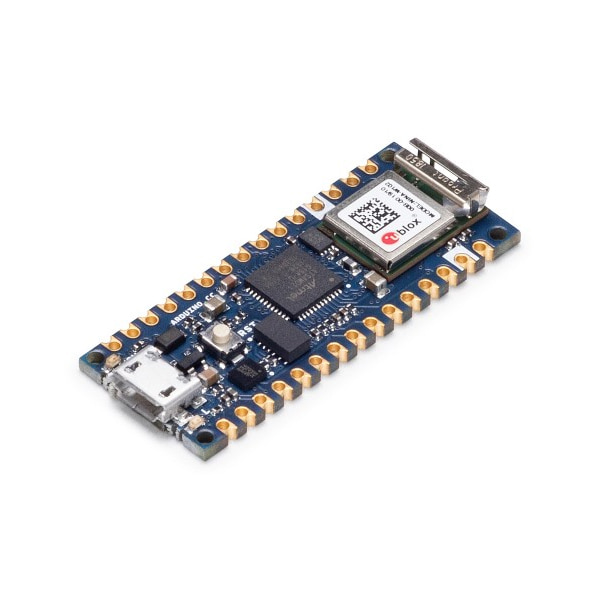
- 본 제품은 정품 아두이노 나노 33 IOT 보드입니다.
- WiFi 및 블루투스 연결을 지원하는 컴팩트하지만 강력한 아두이노 보드입니다.
- Arduino IoT Cloud와 호환되며, full TLS 를 지원합니다.
- ATECC608A 칩에 암호키를 하드웨어 상에 저장할 수 있어 높은 수준의 보안을 제공합니다.
- 아두이노 나노와 동일한 사이즈를 가지고 있으며, SAMD21 MCU 및 ESP32기반 WiFi, BT, 6축 IMU을 지원합니다.
특징
-
This board is based on the SAMD21G18A microcontroller.
Clock up to 48MHz Flash 256KB SRAM 32KB Please note: Arduino Nano 33 IoT only supports 3.3V I/Os and is NOT 5V tolerant so please make sure you are not directly connecting 5V signals to this board or it will be damaged. Also, as opposed to Arduino Nano boards that support 5V operation, the 5V pin does NOT supply voltage but is rather connected, through a jumper, to the USB power input.
To avoid such risk with existing projects, where you should be able to pull out a Nano and replace it with the new Nano 33 IoT, we have the 5V pin on the header, positioned between RST and A7 that is not connected as default factory setting. This means that if you have a design that takes 5V from that pin, it won't work immediately, as a precaution we put in place to draw your attention to the 3.3V compliance on digital and analog inputs.
5V on that pin is available only when two conditions are met: you make a solder bridge on the two pads marked as VUSB and you power the NANO 33 IoT through the USB port. If you power the board from the VIN pin, you won't get any regulated 5V and therefore even if you do the solder bridge, nothing will come out of that 5V pin. The 3.3V, on the other hand, is always available and supports enough current to drive your sensors. Please make your designs so that sensors and actuators are driven with 3.3V and work with 3.3V digital IO levels. 5V is now an option for many modules and 3.3V is becoming the standard voltage for electronic ICs.
The communication on WiFi and Bluetooth is managed by a NINA W102 ESP32 based module. The module is connected to the SAMD21 microcontoller with an SPI BUS and a serial port through the following pins:
SAMD21 Pin SAMD21 Acronym NINA Pin NINA Acronym Description 13 PA8 19 RESET_N Reset 39 PA27 27 GPIO0 Attention Request 41 PA28 7 GPIO33 Acknowledge 23 PA14 28 / 21 GPIO5 / GPIO19 SPI CS / UART RTS 24 PA15 29 / 20 GPIO18 / GPIO22 SPI CLK / UART CTS 22 PA13 1 GPIO21 SPI MISO 21 PA12 36 GPIO12 SPI MOSI 31 PA22 23 GPIO3 Processor TX -> Nina RX 32 PA23 22 GPIO1 NINA TX -> Processor RX Some of the NINA W102 pins are connected to the 15+15 pins headers/pads and can be directly driven by the module's ESP32; in this case it is necessary that the SAMD21 corresponding pins are aptly tri-stated. Below is a list of such signals:
SAMD21 Pin SAMD21 Acronym NINA Pin NINA Acronym Header Description 48 PB03 8 GPIO21 A7 14 PA09 5 GPIO32 A6 8 PB09 31 GPIO33 A5/SCL 7 PB08 35 GPIO5 / GPIO19 A4/SDA The IMU is a LSM6DS3 and it is managed through I2C.
The crypto chip is an ATECC608A and has a supporting library that is used by the WiFiNINA library.
The board has a two 15 pins connectors - one on each side -, pin to pin compatible with the original Arduino Nano.
Pin Funcion Type Description 1 D13/SCK Digital SPI SCK; GPIO 2 +3V3 Power Out Internally generated power output to external devices 3 AREF Analog Analog Reference; can be used as GPIO 4 A0/DAC0 Analog ADC in/DAC out; can be used as GPIO 5 A1 Analog ADC in; can be used as GPIO 6 A2 Analog ADC in; can be used as GPIO 7 A3 Analog ADC in; can be used as GPIO 8 A4/SDA Analog ADC in; I2C SDA; Can be used as GPIO (*) 9 A5/SCL Analog ADC in; I2C SCL; Can be used as GPIO(*) 10 A6 Analog ADC in; can be used as GPIO 11 A7 Analog ADC in; can be used as GPIO 12 VUSB Power In/Out Normally NC; can be connected to VUSB pin of the USB connector by shorting a jumper 13 RST Digital In Active low reset input (duplicate of pin 18) 14 GND Power Power Ground 15 VIN Power In Vin Power input 16 TX Digital USART TX; can be used as GPIO 17 RX Digital USART RX; can be used as GPIO 18 RST Digital Active low reset input (duplicate of pin 13) 19 GND Power Power Ground 20 D2 Digital GPIO 21 D3/PWM Digital GPIO; can be used as PWM 22 D4 Digital GPIO 23 D5/PWM Digital GPIO; can be used as PWM 24 D6/PWM Digital GPIO; can be used as PWM 25 D7 Digital GPIO 26 D8 Digital GPIO 27 D9/PWM Digital GPIO; can be used as PWM 28 D10/PWM Digital GPIO; can be used as PWM 29 D11/MOSI Digital SPI MOSI; can be used as GPIO 30 D12/MISO Digital SPI MISO; can be used as GPIO (*) As opposed to other Arduino Nano boards, pins A4 and A5 have an internal pull up and default to be used as an I2C Bus so usage as analog inputs is not recommended. Opposed to Arduino Nano boards that support 5V operation, the 5V pin does NOT supply voltage but is rather connected, through a jumper, to the USB power input.
On the bottom side of the board, under the communication module, debug signals are arranged as 3x2 test pads with 100 mil pitch. Pin 1 is the bottom left one with the USB connector on the left and the test pads on the right
Pin Function Type Description 1 +3V3 Power Out Internally generated power output to be used as voltage reference 2 SWD Digital SAMD11 Single Wire Debug Data 3 SWCLK Digital In SAMD11 Single Wire Debug Clock 4 UPDI Digital ATMega4809 update interface 5 GND Power Power Ground 6 RST Digital In Active low reset input
문서
-
OSH: Schematics
The Arduino Nano 33 IoT is open-source hardware! You can build your own board using the following files:
EAGLE FILES IN .ZIPSCHEMATICS IN .PDF -
Getting Started
In the Getting Started section, you can find all the information you need to configure your board, use the Arduino Software (IDE), and start to tinker with coding and electronics.