30:1 금속 기어모터 37Dx68L mm -64CPR 인코더
(30:1 Metal Gearmotor 37Dx68L mm with 64 CPR Encoder)
개요
- 본 제품은 강력한 12V 브러쉬 DC 모터입니다.
- 30:1 의 금속 기어박스 및 64 CPR 쿼드라쳐 인코더를 장착하고 있는 제품입니다.
- 한번의 샤프트 회전에 64 카운트의 분해능을 제공하기때문에 기어박스의 출력 샤프트 한 회전당 1920 카운트의 분해능의 제공이 가능합니다.
- 알림: 모터를 스톨시키거나 과부하시키면 모터의 수명을 급격히 줄어들게 하거나 바로 고장이 날수 있습니다. 일반적으로 스톨 전류의 25%이내에서 동작을 추천합니다.
특징
-
Features:
- Working voltage: DC12V
- Gear Ratio: 30:1
- No-Load Speed 366rpm @ 12V
- No-load current 250mA@ 12V:
- Stall Current: 6.5A@ 12V
- Rated Torque 13Kg.cm @ 12V
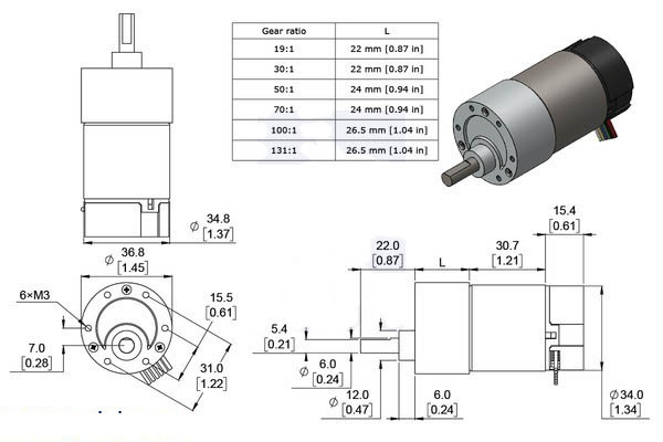
Dimensions:
- Motor Size: 37Dx52L mm
- Shaft Size: 6mm Diameter x 16mm Length
- Weight: 200g
- Lead length: 20cm
문서
-
Using the Encoder
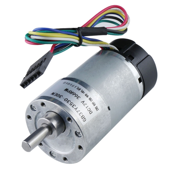
A two-channel Hall effect encoder is used to sense the rotation of a magnetic disk on a rear protrusion of the motor shaft. The quadrature encoder provides a resolution of 64 counts per revolution of the motor shaft when counting both edges of both channels. To compute the counts per revolution of the gearbox output, multiply the gear ratio by 64. The motor/encoder has six color-coded, 8″ (20 cm) leads terminated by a 1×6 female header with a 0.1″ pitch, as shown in the main product picture. This header works with standard 0.1″ male headers and our male jumper and precrimped wires. If this header is not convenient for your application, you can pull the crimped wires out of the header or cut the header off. The following table describes the wire functions:
Color Function Red motor power (connects to one motor terminal) Black motor power (connects to the other motor terminal) Green encoder GND Blue encoder Vcc (3.5 – 20 V) Yellow encoder A output White encoder B output The Hall sensor requires an input voltage, Vcc, between 3.5 and 20 V and draws a maximum of 10 mA. The A and B outputs are square waves from 0 V to Vcc approximately 90° out of phase. The frequency of the transitions tells you the speed of the motor, and the order of the transitions tells you the direction. The following oscilloscope capture shows the A and B (yellow and white) encoder outputs using a motor voltage of 12 V and a Hall sensor Vcc of 5 V:
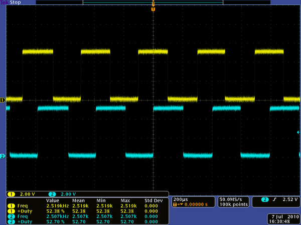
Encoder A and B outputs for 37D mm metal gearmotor with 64 CPR encoder (motor running at 12 V).
By counting both the rising and falling edges of both the A and B outputs, it is possible to get 64 counts per revolution of the motor shaft. Using just a single edge of one channel results in 16 counts per revolution of the motor shaft, so the frequency of the A output in the above oscilloscope capture is 16 times the motor rotation frequency.