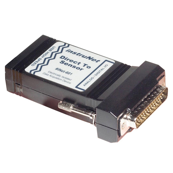
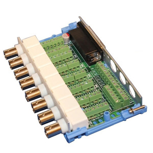
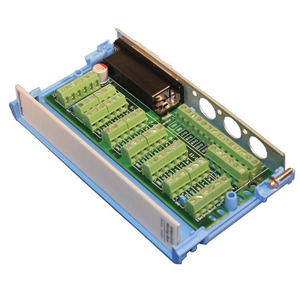
iNet-601 USB DAQ/데이터 로거 -각종 센서 직접 연결
(Standalone USB data acquisition system, 16se/8di,
With Optical Isolation)
개요
- 본 제품은 INet i601 USB DAQ/데이터 로거 장치입니다.
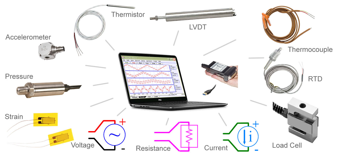
- 전압 센서, 써모커플, 써미스터, RTD 온도센서, 로드셀, 스트레인 게이지, 포텐셔미터, 전류 센서, 저항 센서를 다이렉트로 연결하여 USB 통해 PC와 통신할 수 있게 하여 주는 제품입니다.
- Connect Directly To Sensors: Voltage, Thermocouple, Thermistor, RTD, Load Cell30, Strain Gage30, Potentiometer, Current, Resistance
- 그리고 USB를 통해 PC에서 아날로그 입력, 디지털 입력, 디지털 출력을 제어할 수 있습니다.
- 16개의 single ended 혹은 8개의 differential(차동) 전압 입력 채널을 가지고 있는 데이터 습득 장치로, 매우 정교합니다. 다음 링크 참조 (16se/8di Voltage Input Channels with extremely accurate 24-bit A/D Converter)
- 4개의 디지털 I/O (4mA sink/source, 0 to 3.3V)를 지원합니다.
- 컴팩트한 크기에 튼튼하며, USB로 전원이 공급되는 매우 정교한 데이터 습득용 DAQ 시스템으로 8개나 16개의 서로 다른 센서 타입을 추가적인 신호 conditioning 없이 사용할 수 있습니다.
- i601 제품은 ±36V bank electrical isolation 을 제공하여 예기지 않은 전압으로부터 장비를 보호할 수 있습니다.
- 무료 PC 소프트웨어 instruNet World (iW) SOFTWARE 가 포함되어 있습니다 (다운로드)
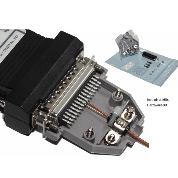
- 센서 연결을 위한 아래 하드웨어 키트와 USB 케이블이 포함되어 있습니다.
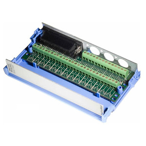
- 또한 옵션으로 별도의 wiring box를 구매하여 연결 또한 가능합니다.


특징
- The i600/i601 USB data logger connects a windows computer to sensors and controls via analogue inputs, digital inputs and digital outputs.
- The i601 product provides ±36V bank electrical isolation; whereas the less costly i600 connects I/O signal ground to computer ground. i60x receives power from USB bus.
- 16se/8di voltage input channels with extremely accurate 24-bit A/D converter.
- 4x digital I/O (4mA sink/source, 0 to 3.3V).
- Connect directly to sensors: voltage, thermocouple, thermistor, RTD, load Cell, strain gage, potentiometer, current, resistance.
-
Product Summary
- This A/D module provides 16se/8di voltage input channels (Ch#1…#16), each of which are independently software programmable with Windows software that support the direct connection to many common sensor types.
- Voltage input range on each channel is independently software programmable to one of: ±20mV, ±40mV, ±80mV, ±150mV, ±300mV, ±600mV, ±1.2V, ±2.5V, ±5V, ±10V
- Included is a mating Hd44 Female Connector & Cover. Alternatively, one can attach i600/i601 to the following optional wiring boxes: i510, i511, If one is working with thermocouples, an i510 wiring box is required due to its internal cold junction compensation.
- i600 and i601 are stand-alone USB data acquisition systems. No additional components, such as external power supply, are required. Included in the box: i60x Hardware Device, USB Cable, Software on CD, Mating Hd44 Female Connector & Hd44 Cover. For details, see the i60x Installation Guide.
- Digitize at a maximum sample rate of 160K sample/sec for 1 channel, 12Ks/sec/ch for 2 channels, 6Ks/sec/ch for 4 channels, and 3Ks/sec/ch for 8 channels. For more details, see Voltage Accuracy.
- Each channel provides the following software programmable parameters: A/D Signal-Averaging-Per-Point (0 … 100mSec), Sample-Rate (samples-per-second-per-channel), Digital IIR Filter (LowPass, HighPass, BandPass, or BandStop), Voltage Measurement Range (±20mV…±10V), Sensor Type, and Single-Ended or Differential Wiring.
- Excitation power (+3.3V ±0.2V, <80mA, 28mA per sensor max) is provided for sensors, along with other End User Power voltages. This 3.3V, which is referenced to instruNet Ground, is automatically readback by A/D when calculating sensor values.
- The 4mA sink/source digital I/O port consists of 4 individual TTL-compatible lines (Ch#25…#28), each of which can be configured as: input or output bit When configured as an input, a channel can be used to sense a digital high (2 to 5.5 Volts) or digital low (0V to 0.8Volts). When configured as an output, a channel can be set high (e.g. >2V) or low (e.g. <0.8V). These I/O pins are short-circuit protected against high voltages up to 6.0V and down to -6.0.
-
Analog Voltage Input (A/D), iNet-600 & iNet-601
Parameter
Specifications
Notes
Description 16se/8di Voltage Input Channels with extremely accurate 24-bit A/D Converter This A/D module provides 16se/8di voltage input channels (Ch#1…#16), each of which are independently software programmable with Windows software that support the direct connection to many common sensor types Absolute Accuracy Specified Error components (i.e. INL, DNL, linearity, noise, temperature drift , time stability) are summed and specified as "Absolute Accuracy" with the following supported sensors (click for accuracy and maximum sample rate): Voltage, Thermocouple, Thermistor, RTD, Load Cell, Strain Gage, Potentiometer, Current, Resistance Voltage Ranges ±20mV … ±10V Voltage input range on each channel is independently software programmable to one of: ±20mV, ±40mV, ±80mV, ±150mV, ±300mV, ±600mV, ±1.2V, ±2.5V, ±5V, ±10V Internal A/D 24-bit Internal 24-bit A/D Converter resolves voltage input range to ±8.4M digital value. Sensors Direct Connect Each of the 8 differential channels support the direct connection to the following sensor types (click for Wiring Diagram and Setup Instructions): Voltage, Thermocouple, Thermistor, RTD, Load Cell, Strain Gage, Potentiometer, Current, Resistance Channel Amplifiers Software Programmable Each channel provides the following software programmable parameters: A/D Signal-Averaging-Per-Point (0 … 100mSec), Sample-Rate (samples-per-second-per-channel), Digital IIR Filter (LowPass, HighPass, BandPass, or BandStop), Voltage Measurement Range (±20mV…±10V), Sensor Type, and Single-Ended or Differential Wiring Wiring Single-Ended or Differential Single-ended (SE) wiring involves measuring the voltage between the input pin and instruNet Ground; whereas Differential (DI) wiring involves measuring the voltage between two input pins Protected Voltage -30 to +30V Short any combination of voltage input channels to external -30 to +30V power source (i.e. capable of high current), instruNet power on or off, any duration, without damage Bandwidth Depends on Voltage Range See absolute accuracy specification tables below (e.g. Voltage Accuracy) for bandwidth details RFI Filter 13 KHz RFI filter
on ≤ ±150mVrangeRFI filter is a low pass filter that rejects high frequencies that could cause small measurement errors if left unfiltered Digital Filter LowPass, HighPass, BandPass, or BandStop Each channel provides optional digital IIR lowpass, highpass, bandpass and bandstop filters with independent software programmable cut-off frequency, minimum dB stopband attenuation, maximum dB passband attenuation, and filter type (e.g. Elliptic, Chebyshev B, Chebyshev S, and Butterworth). Number of poles/zeros (i.e. "filter order") is programmable between 2 and 32. Maximum Sample Rate 160Ks/sec/aggregate Digitize at a maximum sample rate of 160K sample/sec for 1 channel on largest voltage input range. More channels at same voltage input range involves slower rates, e.g. 12Ks/sec per channel for 2 channels, 6Ks/sec/ch for 4 channels, and 3Ks/sec/ch for 8 channels. For a detail on maximum sample rate and bandwidth with different voltage input ranges, sensor types, and a/d averaging; see absolute accuracy specification tables below (e.g. Voltage Accuracy). Sample rate is set accurate to 50 ppm (e.g. user specifies 20000 s/sec yet system digitizes at 20001 s/sec). Minimum sample rate is 0.015 samples/sec/ch. Sensor Excitation Included Excitation power (+3.3V ±0.2V, <80mA, 28mA per sensor max) is provided for sensors, along with other End User Power voltages. This 3.3V, which is referenced to instruNet Ground, is automatically readback by A/D when calculating sensor values. 4x Digital I/O, 4mA sink/source, iNet-600 & iNet-601
Parameter
Specifications
Notes
Description 4 Bidirectional Digital I/O The 4mA sink/source digital I/O port consists of 4 individual TTL-compatible lines (Ch#25…#28), each of which can be configured as: input or output bit. When configured as an input, a channel can be used to sense a digital high (2 to 5.5 Volts) or digital low (0V to 0.8Volts). When configured as an output, a channel can be set high (e.g. >2V) or low (e.g. <0.8V). These I/O pins are short-circuit protected against high voltages up to 6.0V and down to -6.0V. Function input or output bit Each bit is independently software programmed as an input or output TTL Compatible Yes Supports 0.8V for logic 0 and 2V for logic 1, which is typical for TTL 3.3V CMOS Compatible " Supports 1.1V (3.3V*.35) for logic 0 and 2.3V (3.3V*.7) for logic 1, which is typical for digital Cmos powered by 3.3V Drive Relay Directly " Wire one side of external relay coil to power supply (e.g. 5V), wire other side to I/O pin, and output logic 0 to turn on relay Detect Switch Closure " Wire one side of external switch to and, wire other side to I/O pin, input logic 0 when switch is closed, and input logic 1 when switch is open Physical/Environmental Specifications, iNet-600 & iNet-601
Parameter
Specifications
Notes
I/O Connector HD44 male High density 44 pin male connector (e.g. Astron #HD6C-44-AMAN-1G213 , click footnote for datasheet, outer shell is same size as DB25) Wiring Box Compatible Compatible with the following optional wiring boxes: i510, i511, i512 Physical Dimensions 3.784″ x 0.924″ x 2.286″ For details, see i60x Mechanical Drawing Operating Temp. 1 to 70°C Operate in temperature between 1°C and 70°C, no condensation Storage Temperature -20 to 70°C Store in ambient temperature between -20°C and +70°C Relative Humidity ≤ 90% Operate in humidity less than 90%, no condensation Hot Plug & Play Yes One can attach device with power on or off, without damage USB Interface 2.0 Transfer data to/from device at 480Mbits/sec Safety IEC, EN, UL, CSA Designed to meet IEC 61010-1, EN 61010-1, UL 61010-1, CSA 61010-1 Emissions EN, CE, FCC Designed to meet EN 61326 EMC Min Immunity, EN 55011 Emissions Group 1 Class A, CE, C-tick, ICES, and FCC Part 15 Emissions Class A CE Compliance Yes Meets 73/23/EEC low-voltage safety, and 89/336/EEC electromagnetic compatibility Specifications Subject to change All specifications are subject to change without notice +5V USB Power, Max +5V ±0.4V, ~433mA Power drawn from USB bus, with max load from end user sensors +5V USB Power, Type +5V ±0.4V, ~255mA Power drawn from USB bus, with no load from end user sensors
문서
-
Subjects Discussed in this Datasheet, iNet-600 & iNet-601 - Analog Voltage Input (A/D), Electrical Specifications, Software Interface
- 4x Digital I/O (4mA sink/source, 0 to 3.3V), Electrical Specifications, Software Interface
- I/O Software Channels
- Hd44 Connector Pins
- Power Available to End User
- Physical/Environmental Specifications
- Voltage Measurement Absolute Accuracy Specifications
- Voltage Measurement Drift Errors
- Thermocouple Measurement Absolute Accuracy Specifications
- Thermistor Measurement Absolute Accuracy Specifications
- RTD Measurement Absolute Accuracy Specifications
- Load Cell Measurement Absolute Accuracy Specifications
- Strain Gage Measurement Absolute Accuracy Specifications
- Potentiometer Measurement Absolute Accuracy Specifications
- Current Measurement Absolute Accuracy Specifications
- Resistance Measurement Absolute Accuracy Specifications
- Connect EXCEL directly to Sensors via USB Data Acquisition Hardware
- Connect LabVIEW directly to Sensors with USB Data Acquisition Hardware
- Connect DASYLab directly to Sensors via USB Data Acquisition Hardware
- Connect MATLAB directly to Sensors via USB Data Acquisition Hardware
- Connect Origin Software to Sensors via USB Data Acquisition Hardware
- Programming in C or Basic
- Application Software
- Compatible Sensors and Controls
- Advanced Techniques
- Compare With Other Products
- Getting Started