DC 전류 센서 0-2A
(CE-IZ02-32MS2-0.2 DC Current Sensor 0-2A)
개요
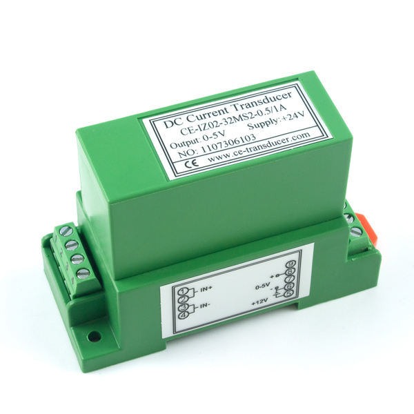
- 본 제품은 0A-2A의 전류 측정이 가능한 전류 센서입니다.
- 12VDC로 동작하며 0-5VDC의 아날로그 전압 출력을 측정된 전류에 따라 출력합니다.
- 본 제품은 스크류나 35mm DIN 레일에 쉽게 설치할 수 있으며, 터미널 블럭은 AWG#16 등급의 전선까지 삽입이 가능합니다.
- 측정되는 전류가 제품의 허용 입력 전류보다 높을 경우 5V이상의 출력 전압이 나타날 수 있습니다. 이럴 경우 5V 아날로그 전압까지 입력 받는 아두이노나 기타 5V 보드의 경우 손상 받을 수 있으니 주의 하시기 바랍니다.
- 아날로그 전압 입력을 가진 제품과 사용이 가능하며 센서 값을 전압으로 변환하는 공식은 아래와 같습니다
- I(mA) = SensorValue
특징
-
Product Specifications
Sensor Properties
Sensor Type Current (DC In-Line) Sensor Output Type Non-Ratiometric Input Current Min 0 A Input Current Max 2 A Measurement Error Max 0.2 % Sensor Response Time Max 15 ms
Electrical Properties
Supply Voltage Min 12 V DC Supply Voltage Max 12 V DC Current Consumption Max 16.7 mA Output Voltage Min 0 V DC Output Voltage Max 5 V DC Isolation Voltage (DC) 2.5 kV DC Isolation Voltage (AC) 1.5 kV AC
Physical Properties
Material Plastic Recommended Wire Size 12 - 24 AWG Operating Temperature Min 0 °C Operating Temperature Max 50 °C -
Recommended Power Supplies
- 3024 – Power Supply 12VDC 2.0A (North American style plug)
- 3023 – Power Supply 12VDC 2.0A (European style plug)
- 3025 – Power Supply 12VDC 2.0A (UK style plug)
- 3022 – Power Supply 12VDC 2.0A (Australian style plug)
In order to use one of these power supplies with this sensor, you must cut the small plug from the end of the power supply and connect the wires directly into the sensor. You can also use a 3031 – Female Pigtail.
-
Connection
This sensor connects to any device with an Analog Input.You can use the 1144 - 12V Sensor Adapter to connect the voltage sensor to an analog input as pictured below.

- Connect the +12V terminal on the 1144 to the voltage sensor terminal 5 (+12V).
- Connect the GND terminal on the 1144 to the voltage sensor terminal 6 (-).
- Connect the ANLG terminal on the 1144 to the voltage sensor terminal 8 (+).
Alternatively, you can use the 3002 - Sensor Cable 60cm or the3004 - Sensor Cable 350cm to connect the DC Current Sensor to your Phidget. Just snip off the connector from one end of the sensor cable and connect the wires as described below. You can also use a3031 – Female Pigtail if you don't want to cut the barrel jack off of the power supply.
- Connect the Power Supply +12V wire (the wire with the white line) to the Current Sensor terminal 5 (+12V).
- Connect the Power supply Ground wire and the Analog Sensor Cable Black wire to the Current Sensor terminal 6 (-).
- Connect the sensor cable white wire to the Current Sensor terminal 8 (+).
- Connect the positive wire of the device's power supply to the Current Sensor terminal marked 1 (IN+).
- Connect a wire from the input voltage of the device under test to the Current Sensor terminal 3 (IN-).
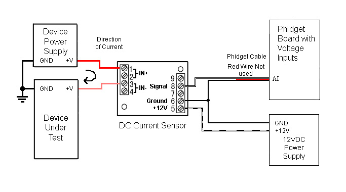

For boards that have power input, such as the 1019 or the 1073, if the supplied power is 12V, then the + terminal block on the Phidget Board can be connected to the voltage sensor terminal 5 (+12V), and the G terminal block on the Phidget Board can be connected to the sensor terminal 6 (-).


