3축 가속도계 및 3축 자이로센서 LSM6DSL 모듈
(LSM6DSL click)
개요
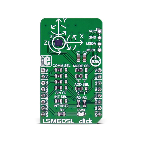
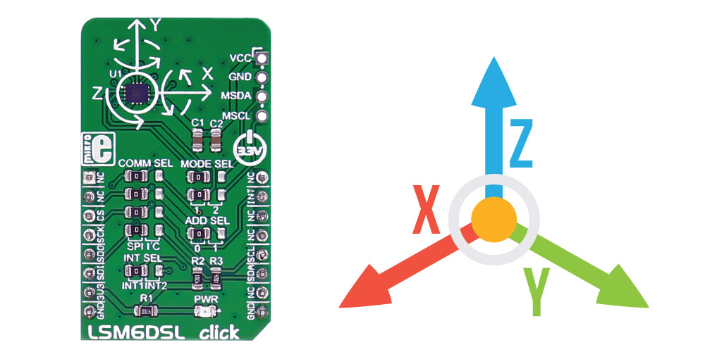
- 본 제품은 3축 가속도계 및 3축 자이로센서 LSM6DSL 모듈입니다.
- 3.3V로 동작하며, MCU와 SPI나 I2C로 통신합니다.
특징
-
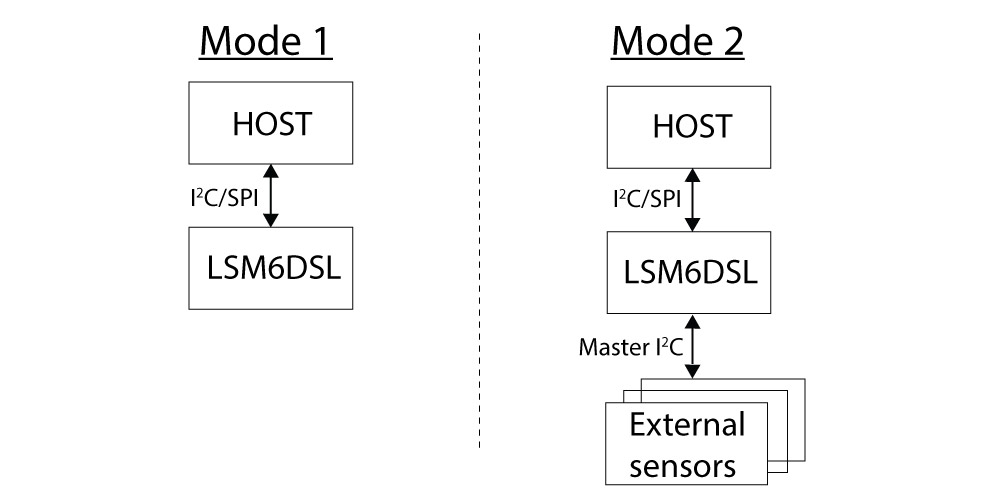
Mode 1: I2C slave interface or SPI serial interface is available.
Mode 2: I2C slave interface, or SPI serial interface and I2C interface master for external sensor connections, are available.
LSM6DSL inertial module features
The LSM6DSL is a system-in-package featuring a 3D digital accelerometer and a 3D digital gyroscope performing at 0.65 mA in high-performance mode and enabling always-on low-power features for an optimal motion experience.
The event-detection interrupts enable efficient and reliable motion tracking and contextual awareness, implementing hardware recognition of free-fall events, 6D orientation, click and double-click sensing, activity or inactivity, and wakeup events
The LSM6DSL has a full-scale acceleration range of ±2/±4/±8/±16 g and an angular rate range of ±125/±245/±500/±1000/±2000 dps (degrees per second).
Specifications
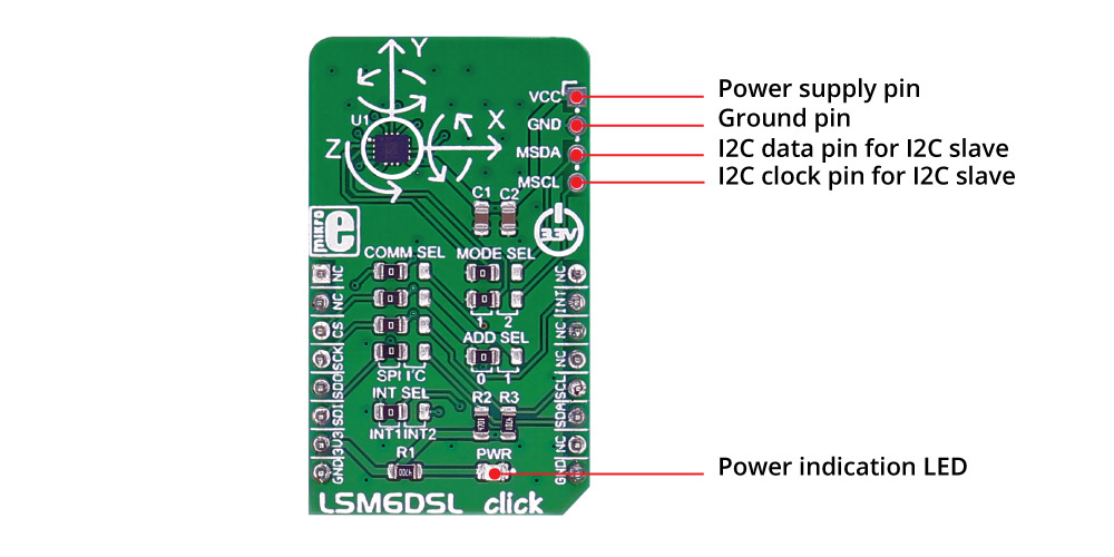
Type Motion Applications Motion tracking and gesture detection, indoor navigation, vibration monitoring and compensation, etc. On-board modules LSM6DSL Key Features Power consumption: 0.4 mA in combo normal and 0.65 mA in combo high-performance mode; hard, soft ironing for external magnetic sensor corrections Interface I2C,SPI Input Voltage 3.3V Click board size M (42.9 x 25.4 mm) Pinout diagram
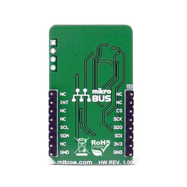
This table shows how the pinout on LSM6DSL click corresponds to the pinout on the mikroBUS™ socket (the latter shown in the two middle columns).
Notes Pin 
Pin Notes NC 1 AN PWM 16 NC NC 2 RST INT 15 INT Programmable interrupt Chip select CS 3 CS TX 14 NC SPI clock SCK 4 SCK RX 13 NC Master input slave output MISO 5 MISO SCL 12 SCL I2C clock Master output slave input MOSI 6 MOSI SDA 11 SDA I2C data Power supply +3.3V 7 3.3V 5V 10 NC Ground GND 8 GND GND 9 GND Ground Jumpers and settings
Designator Name Default Position Default Option Description JP1 COMM SEL Left SPI Communication Interface Selection SPI/I2C, left position SPI, right position I2C JP2 COMM SEL Left SPI Communication Interface Selection SPI/I2C, left position SPI, right position I2C JP3 COMM SEL Left SPI Communication Interface Selection SPI/I2C, left position SPI, right position I2C JP4 INT SEL Left INT1 Interrupt selection INT1/INT2, left position INT1, right position INT2 JP5 COMM SEL Left SPI Communication Interface Selection SPI/I2C, left position SPI, right position I2C JP6 MODE SEL Left 1 Mode Selection 1/2, left position 1, right position 2 JP7 MODE SEL Left 1 Mode Selection 1/2, left position 1, right position 2 JP8 ADD SEL Left 0 I2C slave address selection 0/1, left position 0, right position 1
문서
연관제품
- 연관제품 1