팬 컨트롤러 MAX31760 모듈 - 온도측정
(Fan 2 click)
개요
- 본 제품은 MAX31760 팬 스피드 컨트롤러 모듈입니다.
- PWM 신호를 이용하여 팬이 속도를 조절할 수 있습니다.
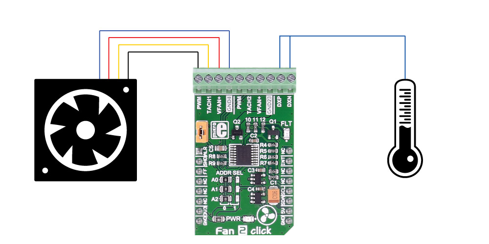
- 온도에 따라 팬의 회전 속도를 조절하여 원하는 온도레벨을 유지할 수 있게, 온도를 측정할 수 있습니다.
- 예를들어 25도로 온도를 설정하면, 25도 이상이 되면 팬이 동작할 수 있게 합니다.
- 3.3V, 5V로 동작하며 MCU와는 I2C 인터페이스로 통신합니다.
특징
-
MAX31760 controller features
The MAX31760 integrates temperature sensing along with precision PWM fan control. It accurately measures its local die temperature and the remote temperature of a discrete diode-connected transistor, such as a 2N3906, or a thermal diode commonly found on CPUs, graphics processor units (GPUs), and other ASICs. Multiple temperature thresholds, such as local high/overtemperature (OT) and remote high/overtemperature, can be set by an I2C-compatible interface.
Fan speed is controlled based on the temperature reading as an index to a 48-byte lookup table (LUT) containing user-programmed PWM values. The flexible LUT-based architecture enables the user to program a smooth nonlinear fan speed vs. temperature transfer function to minimize acoustic fan noise. Two tachometer inputs allow measuring the speeds of two fans independently.See the datasheet for more information.
How it works
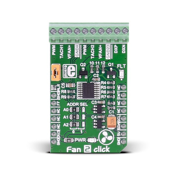
The click carries a 10-pole terminal block, that allows easy connection for pairs of two, three or four wire DC fans, on the standard way of connection via PWM, TACH, GND, VFAN lines.
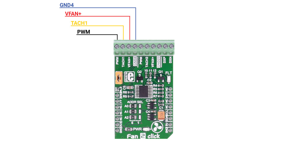
A single onboard jumper setting enables 2 or 3 wire fan connection. In addition, there are two points (DXP, DXN) on the same terminal for external temperature sensor connection. The click communicates with the MCU over data interface voltage level of 3.3V only.Specifications
Type DC Applications For speed control of DC fans (5/12 VDC) than could be found on PCs, servers, network equipment, set-top-box and digital-video-recorder devices, and many other consumer electronics, or storage containers like RAID systems etc. On-board modules MAX31760 precision fan-speed controller Key Benefits Temperature sensor Interface I2C Input Voltage 3.3V or 5V Click board size M (42.9 x 25.4 mm) Pinout diagram
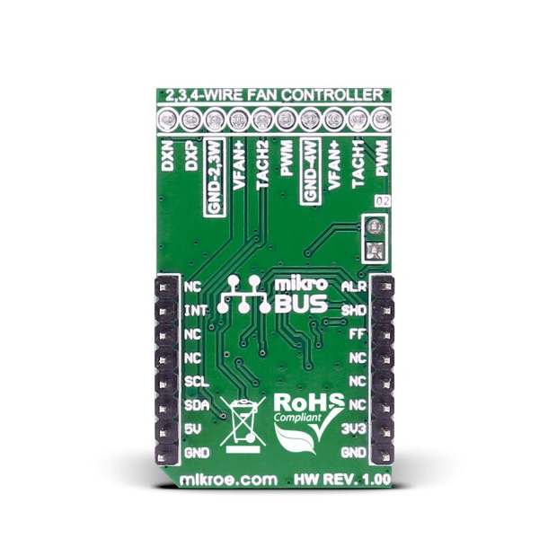
This table shows how the pinout on Fan 2 click corresponds to the pinout on the mikroBUS™ socket (the latter shown in the two middle columns).
Notes Pin 
Pin Notes #ALERT, active low, local/remote overtemperature fault ALR 1 AN PWM 16 NC #SHDN, active low overtemperature shutdown fault SHD 2 RST INT 15 INT #INT, active low, at least one of the three faults has occurred #FANFAULT, active low, fan speed fault FF 3 CS TX 14 NC NC 4 SCK RX 13 NC NC 5 MISO SCL 12 SCL SCL I2C line NC 6 MOSI SDA 11 SDA SDA I2C line Power supply +3.3V 7 3.3V 5V 10 +5V Power supply Ground GND 8 GND GND 9 GND Ground Jumpers and settings
Designator Name Default Position Default Option Description J1 FAN SEL ON or OFF (not specified) 2/3 or 4 wire fan When in place (ON position) it enables two or three wire fan usage, in otherwise (OFF - unconnected) it enables 4-wire fan applications.
문서
연관제품
- 연관제품 1