4자리 알파뉴메릭 도트 매트릭스 모듈 -I2C, 빨강
(4Dot-Matrix R click)
개요
- 본 제품은 5x7 도트 크기의 문자 4개를 디스플레이 할 수 있는 디스플레이 모듈입니다.
- 오슬람사의 5x7 알파뉴메릭 디스플레이 SLO2016를 MCP23017 I2C 포트 확장기와 결합하여 I2C 인터페이스만으로 디스플레이를 제어할 수 있게 디자인한 제품입니다.
- 3.3V나 5V로 동작하며, 디스플레이의 색은 빨강입니다.
특징
-
How 4Dot-Matrix R click works
The SLO2016 module is paired up with the MCP23017 I2C port expander for easier use and minimal command lines.
Data is sent via the I2C expander. D0-D6 are used to select ASCII character from internal memory. A0 and A1 bits are used to select which place takes which character (1,2,3,4).
Detailed instructions are provided in the modules datasheet. The PWM pin is intended for blanking the display, and it can also be used for dimming the display.
The CLR function clears the ASCII characters RAM.SLO2016 features
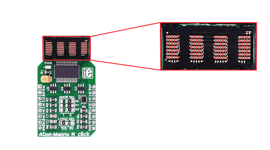
SLO2016 is a 4-Digit 5x7 Dot Matrix Alphanumeric intelligent display, with many built-in functions that will save your time. The integrated circuit contains memory, a 128 ASCII ROM decoder, multiplexing circuitry and drivers.
The character set consists of 128 special ASCII characters for English, German, Italian, Swedish, Danish, and Norwegian. So, you don't need to build a character set yourself.
You also have direct access to each digit independently and asynchronously.Specifications
Type LED Matrix Applications 4 characters of 5x7 dots display to your device On-board modules SLO2016 5 x 7 dot matrix display, MCP23017 port expander Key Features Built-in Memory, Built-in Character Generator, Built-in Multiplex and LED Drive Circuitry, Superior ESD Immunity, readability up to eight feet (2.5m) Key Benefits 128 Special ASCII Characters for English, German, Italian, Swedish, Danish, and Norwegian. Interface I2C Input Voltage 3.3V or 5V Click board size M (42.9 x 25.4 mm) Pinout diagram
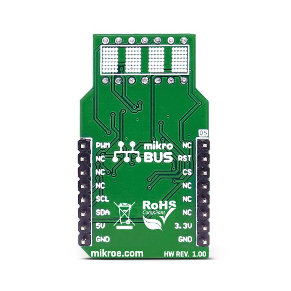
This table shows how the pinout on 4Dot-Matrix R click corresponds to the pinout on the mikroBUS™ socket (the latter shown in the two middle columns).
Notes Pin 
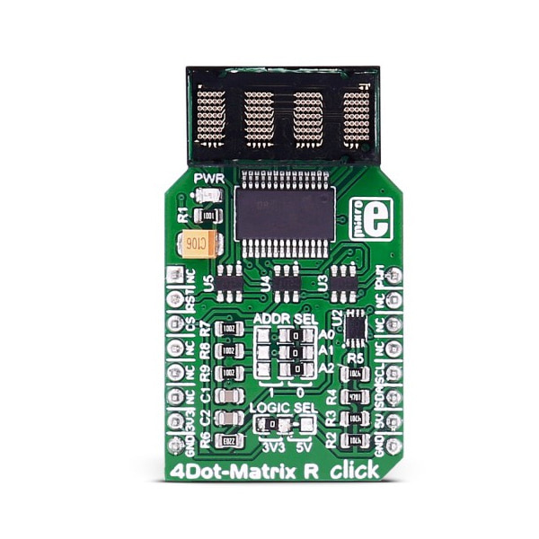
Pin Notes NC 1 AN PWM 16 PWM Display blanking and PWM Clear module RAM RST 2 RST INT 15 NC NC 3 CS TX 14 NC NC 4 SCK RX 13 NC NC 5 MISO SCL 12 SCL I2C clock NC 6 MOSI SDA 11 SDA I2C data Power supply +3.3V 7 3.3V 5V 10 +5V Power supply Ground GND 8 GND GND 9 GND Ground Jumpers and settings
Designator Name Default Position Default Option Description ADDR SEL A0/A1/A2 0 0 I2C slave address selection LOG SEL Interface power supply 5V Logic Level Voltage Selection 3V3/5V, left position 3V3, right position 5V
4Dot-Matrix R click features a jumper for setting the voltage logic level. By default, it's soldered to a 5V position.
문서
연관제품
- 연관제품 1