MEMS 디지털 압력 센서 MS5525DSO-SB001GS 모듈
(Manometer 2 click)
개요
- 본 제품은 MEMS 디지털 압력 센서 MS5525DSO-SB001GS 모듈입니다.
- 3.3V에서 동작하게 디자인이 되어 있으며 MCU와 I2C 혹은 SPI 인터페이스로 통신합니다.
- 센서는 24비트의 대기압 정보와 온도를 제공합니다.
특징
-
MS5525DSO-SB001GS features
The MS5525DSO-SB001GS is a new generation of Digital Small Outline pressure sensors with SPI and I2C bus interface designed for high volume OEM users.
The sensor module includes a pressure sensor and an ultra-low power 24-bit ∆Σ ADC with internal factory calibrated coefficients. It provides a 24-bit digital pressure and temperature value and different operation modes that allow the user to optimize for conversion speed and current consumption.
The MS5525DSO-SB001GS consists of a piezo-resistive sensor and a sensor interface IC. The main function of the MS5525DSO-SB001GS is to convert the uncompensated analog output voltage from the piezo-resistive pressure sensor to a 24-bit digital value, as well as providing a 24-bit digital value for the temperature of the sensor.
How it works
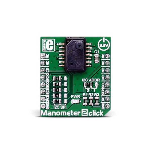
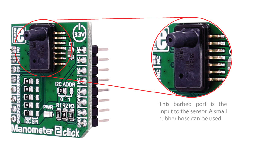
Manometer 2 click measures absolute pressure of 1PSI max, trough the barbed port.
You can choose between SPI and I2C communication.
Specifications
Type Pressure,Altitude Applications Factory automation, altitude and airspeed measurements, medical instruments, leak detection, etc. On-board modules MS5525DSO digital pressure sensor Key Benefits 24-bit digital pressure and temperature value Interface I2C,SPI Input Voltage 3.3V Click board size S (28.6 x 25.4 mm) Pinout diagram
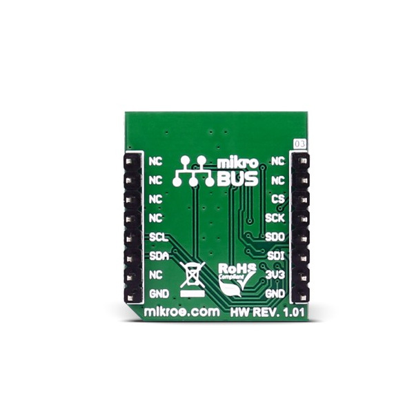
This table shows how the pinout on Manometer 2 click corresponds to the pinout on the mikroBUS™ socket (the latter shown in the two middle columns).
Notes Pin 
Pin Notes NC 1 AN PWM 16 NC NC 2 RST INT 15 NC Chip Select CS 3 CS TX 14 NC SPI Clock SCK 4 SCK RX 13 NC SPI Master Input Slave Output MISO 5 MISO SCL 12 SCL I2C Clock SPI Master Output Slave Input MOSI 6 MOSI SDA 11 SDA I2C Data Power supply +3.3V 7 3.3V 5V 10 NC Ground GND 8 GND GND 9 GND Ground Jumpers and settings
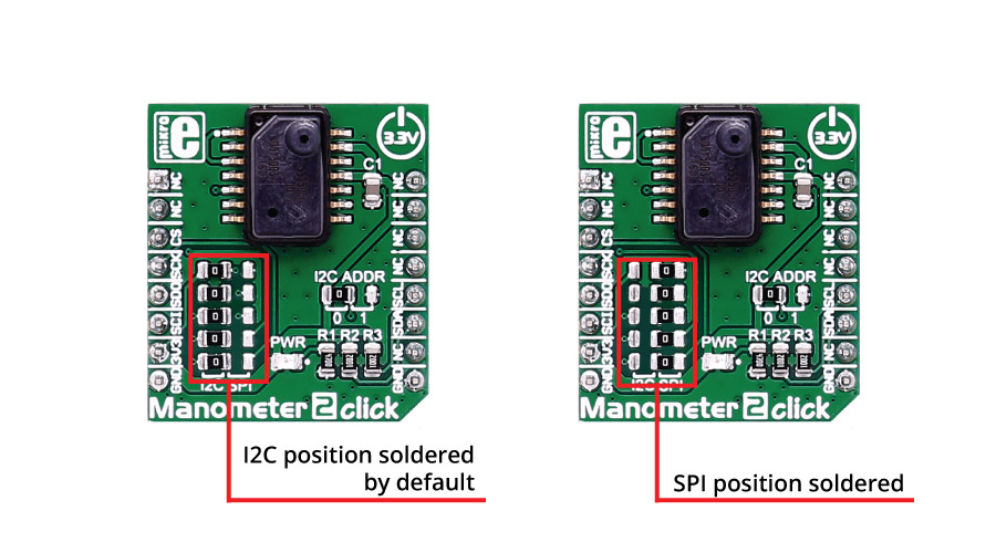
In order to set the SPI interface, you need to move all the 5 jumpers (JP1-JP5).
These jumpers are soldered in I2C interface position by default.
There is an option to select the alternate address with jumper J6 in the case of I2C interface (default position is logic 0).
문서
연관제품
- 연관제품 1