고속 CAN 트랜시버 ATA6563 모듈 -CAN FD 지원
(ATA6563 click)
개요
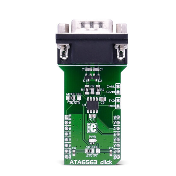
- 본 제품은 ATA6563 고속 CAN 트랜시버 모듈입니다.
- 5V로 전원으로 동작하며, VIO SEL 점퍼를 이용하여 3.3V나 5V 로직레벨을 선택할 수 있습니다.
- 타켓 MCU와 UART로 통신합니다.
- CAN FD(Flexisble Data-rate)를 지원하여 클래식 CAN 장치보다 데이터 전송 속도가 빠릅니다.
특징
-
ATA6563 features
The ATA6563 is a high-speed CAN transceiver that provides an interface between a controller area network (CAN) protocol controller and the physical two-wire CAN bus.
The transceiver is designed for high-speed (up to 5 Mbps) CAN applications in the automotive industry, providing differential transmit and receive capability to (a microcontroller with) a CAN protocol controller. It offers improved electromagnetic compatibility (EMC) and electrostatic discharge (ESD) performance.
The transceiver is CAN FD (Flexible data-rate) ready, meaning it has increased data rates in comparison with classic CAN.How the click works
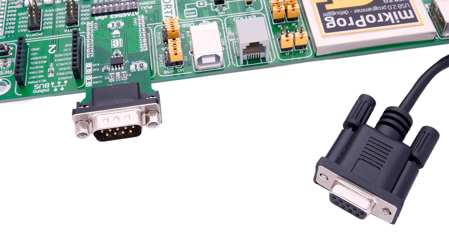
ATA6563 click is connected to a CAN bus via the DB9 cable, which then communicates with the network.
Specifications
Type CAN Applications Classical CAN and CAN FD networks in Automotive, Industrial, Aerospace, Medical and Consumer applications. On-board modules ATA6563 high-speed CAN transceiver from Microchip Key Features Optimized for CAN FD at 2 and 5 Mbps operation, maximum propagation delay: 210ns; the chip supports CAN 2.0 and CAN with flexible data rates. Interface UART Input Voltage 3.3V or 5V Click board size L (57.15 x 25.4 mm) Pinout diagram
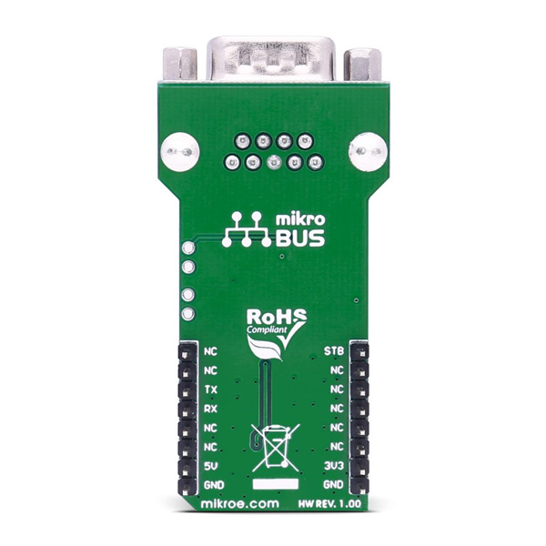
This table shows how the pinout on ATA6563 click corresponds to the pinout on the mikroBUS™ socket (the latter shown in the two middle columns).
Notes Pin 
Pin Notes Standby select STBY 1 AN PWM 16 NC NC 2 RST INT 15 NC NC 3 CS TX 14 RX UART data receive NC 4 SCK RX 13 TX UART data transmit NC 5 MISO SCL 12 NC NC 6 MOSI SDA 11 NC Power supply +3.3V 7 3.3V 5V 10 +5V Power supply Ground GND 8 GND GND 9 GND Ground Jumpers and settings
Designator Name Default Position Default Option Description JP1 VIO SEL Left 3V3 VIO Supply Voltage Selection 3V3/5V, left position 3V3, right position 5V JP2 MODE SEL Left ON Selection of the standby feature; default is always on, right option switches to the STB pin on the mikroBUS™ Additional pins
Name I/O Description CANL I/O CAN lines, same as on DB9 connector CANH I/O CAN lines, same as on DB9 connector TXD I UART lines, same as on the mikroBUS™ RXD O UART lines, same as on the mikroBUS™
문서
연관제품
- 연관제품 1