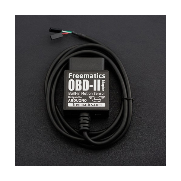
프리매틱스 OBD-II UART 어답터 V2 (아두이노용)
(Freematics OBD-II UART Adapter V2 (for Arduino))
개요
- 본 제품은 차량의 OBD-II 포트의 데이터를 UART로 아두이노에 전송하여 주는 아답터입니다.
- 전용 아두이노 라이브러리를 이용하여 사용이 가능하며, OBD-II 데이터 및 6축 MEMS 모션 센서, 자동차 배터리 전압 측정을 위한 voltmeter를 제공합니다.
- 본 아답터는 OBD-II 포트에서 전원을 끌어다 5V(최대 2.1A까지)로 변환하여 자체 전원 및 아두이노와 같은 부착된 장치의 전원을 공급할 수 있습니다.
특징
- Access to all standard OBD-II PIDs with extended ELM327 AT command-set
- Built-in MPU-6050 MEMS module (accelerometer, gyroscope & temperature)
- Built-in voltage meter for measuring car battery voltage
- DC 5V/2.1A power supply for host device
- Serial UART data interface for use with micro-controllers
- USB interface for use with PC, laptop, tablet and single board computer
- Supporting CAN bus & KWP2000 protocols
- Reading and clearing vehicle diagnostic trouble code (engine & powertrain only)
- Low power mode @6mA
- Arduino library and sketches available
-
Compatibility
The adapter plugs into the OBD port usually located under the steering column or slightly to the left of it. To check if your vehicle is OBD-II certified, open your hood and find the sticker that looks like this:
Vehicles using following vehicle protocols are supported.
- CAN 500Kbps/29bit
- CAN 500Kbps/11bit
- CAN 250Kbps/29bit
- CAN 250Kbps/11bit
- KWP2000 Fast
- KWP2000 5Kbps
- ISO9141-2
The OBD-II Adapter is compatible with all Arduino range including Arduino UNO, Arduino Leonardo, Arduino Micro, Arduino Nano, Arduino Mini, Arduino Pro Mini, Arduino MEGA 1280/2560/ADK.
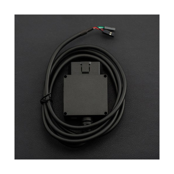
ConnectorsThe adapter stays plugged into the OBD port usually located under the steering column or slightly to the left of it. A cable comes out from the adapter and splits into one 4-pin connector two 2-pin connectors, including power lines (VCC/GND) and data lines (Rx/Tx). They can be connected to Arduino with onboard breakout pins or breakout shield. Your Arduino device will look tidy in car with only one cable.
Power Connector (2-pin 2.54 Dupont connector)
- Red: VCC (connecting to Arduino's VCC)
- Black: GND (connecting to Arduino's GND)
Serial UART Data Connector (2-pin 2.54 Dupont connector)
- White: Rx (connected to Arduino's serial Tx)
- Green: Tx (connected to Arduino's serial Rx)
USB Port
- For connection with computer or tablet via micro USB cable
- For power output (5V/2A)
문서
-
Extended ELM327 Command Set
We have extended standard ELM327 command set for following purposes:
- Multiple (up to 8) OBD-II PIDs reading from a single query
- Accessing built-in MEMS module (MPU-6050)
- Accessing built-in voltmeter (measuring battery voltage)
Following are the added commands:
ATACL
- Function: reading accelerometer data
- Response: X/Y/Z values from accelerometer in format of X,Y,Z
ATGYRO
- Function: reading gyroscope data
- Response: X/Y/Z values in the format X,Y,Z
ATTEMP
- Function: reading temperature data
- Response: temperature (raw) data
ATRV
- Function: reading car battery voltage
- Response: voltage value
The Arduino library has API implemented with all the extended commands.
Library
A dedicated Arduino library is provided for easy access to all the features with any type of Arduino.
Some commonly used APIs are like following:
- setBaudRate - set adapter serial baudrate
- readPID - read specified OBD-II PID and return parsed value
- clearDTC - clear diagnostic trouble code
- getVoltage - measure car battery voltage
- getVIN - retrieve Vehicle Identification Number
- getTemperature - get device temperature
- readAccel - read accelerometer X/Y/Z values
- readGyro - read gyroscope X/Y/Z values
There are more extensive APIs experts. Please refer to the library header file for more information.
Here is an example Arduino sketch of a simplest engine RPM indicator, which uses the pin 13 LED (built in on Arduino board) to indicate whether the engine is above 3000 rpm.
#include <OBD2UART.h> COBD obd; void setup() { // we'll use the debug LED as output pinMode(13, OUTPUT); // start communication with OBD-II adapter obd.begin(); // initiate OBD-II connection until success while (!obd.init()); } void loop() { int value; // save engine RPM in variable 'value', return true on success if (obd.readPID(PID_RPM, value)) { // light on LED on Arduino board when the RPM exceeds 3000 digitalWrite(13, value > 3000 ? HIGH : LOW); } }A more comprehensive example sketch can be found here.
Some commonly used PIDs are defined in OBD library as following.
Engine
- PID_RPM – Engine RPM (rpm)
- PID_ENGINE_LOAD – Calculated engine load (%)
- PID_COOLANT_TEMP – Engine coolant temperature (°C)
- PID_ENGINE_LOAD – Calculated Engine load (%)
- PID_ABSOLUTE_ENGINE_LOAD – Absolute Engine load (%)
- PID_TIMING_ADVANCE – Ignition timing advance (°)
- PID_ENGINE_OIL_TEMP – Engine oil temperature (°C)
- PID_ENGINE_TORQUE_PERCENTAGE – Engine torque percentage (%)
- PID_ENGINE_REF_TORQUE – Engine reference torque (Nm)
Intake/Exhaust
- PID_INTAKE_TEMP – Intake temperature (°C)
- PID_INTAKE_PRESSURE – Intake manifold absolute pressure (kPa)
- PID_MAF_FLOW – MAF flow pressure (grams/s)
- PID_BAROMETRIC – Barometric pressure (kPa)
Speed/Time
- PID_SPEED – Vehicle speed (km/h)
- PID_RUNTIME – Engine running time (second)
- PID_DISTANCE – Vehicle running distance (km)
Driver
- PID_THROTTLE – Throttle position (%)
- PID_AMBIENT_TEMP – Ambient temperature (°C)
Electric Systems
- PID_CONTROL_MODULE_VOLTAGE – vehicle control module voltage (V)
- PID_HYBRID_BATTERY_PERCENTAGE – Hybrid battery pack remaining life (%)
Additional defines can be added to access all OBD-II PIDs which the car's ECU provides.
Comparison
The following table lists the differences among different Freematics OBD-II adapter models.
Features \ Models OBD-II I2C Adapter OBD-II UART Adapter V1 OBD-II UART Adapter V2 Connection Interface I2C Serial UART Serial UART Additional Interface N/A N/A microUSB MEMS Sensor MPU-6050 N/A MPU-6050 Voltmeter Yes Yes Yes Max. Output Power 2A 2A 2.1A Standby Mode Power 10mA 5mA 6mA FAQ
Q: What is this product used for?
A: The most straight-forward use of this product is for making Arduino possible to access vehicle data easily. The OBD-II data, together with other data from GPS or all kinds sensors, can be logged and stored on SD/TF card with Arduino and that makes an open-source vehicle data logger (check out the data logger kits). More extensively, many interesting interaction applications requiring car data can be made.Q: How is the adapter powered?
A: The adapter gets power from the 12V DC output from the OBD-II port.Q: Does my Arduino needs power from somewhere in the car?
A: The adapter provides regulated 5V output for powering Arduino and other devices, so no extra power cord is needed.Q: Do I need a CAN bus shield to use with the adapter?
A: Definitely no. The adapter retrieves data from CAN bus, like a CAN bus shield does and convert the more complicated CAN bus interface to simple serial UART interface which Arduino and most embedded systems are easy to access. The data connection is provided by adapter's data connector (Rx and Tx).Q: How do I connect the adapter with my Arduino?
A: The adapter works with all models of Arduino with the dedicated Arduino library and is connected with Arduino by connecting adapter's Tx to Arduino's Rx (D0) and adapter's Rx to Arduino's Tx (D1). If you want to connect and disconnect the adapter with your Arduino effortlessly, it's recommended to use a common I/O breakout shield or use an Arduino board with breakout pins for Rx/Tx/VCC/GND.Q: Is the power provided by the adapter always available in car?
A: This depends on whether the OBD-II port of your car still has power after ignition is off. Actually it is so with most cars.Q: What's the maximum frequency of data polling?
A: The OBD-II PIDs are polled one after another. The time for a polling depends on the speed of car's ECU computer and how busy the computer is in different status. With a typical modern car with CAN bus, the time can be as low as 10ms. In other word, up to 100 times of data polling can be done in one second.
연관제품
- 연관제품 1