

MAX22200 시리얼 솔레노이드/모터 드라이버 -SPI
(H-BRIDGE 11 CLICK)
개요
- 본 제품은 MAX22200 시리얼 솔레노이드/모터 드라이버 -SPI입니다.
- 전압을 부하에 인가하여 양쪽 방향으로 동작할 수 있게 하여 주는 제품입니다.
- SPI로 설정할 수 있는 octal serial-controlled solenoid and motor driver MAX22200 칩을 탑재하고 있습니다.
- 4.5V-36V 전압범위에서 동작합니다.
특징
-
HOW DOES IT WORK?
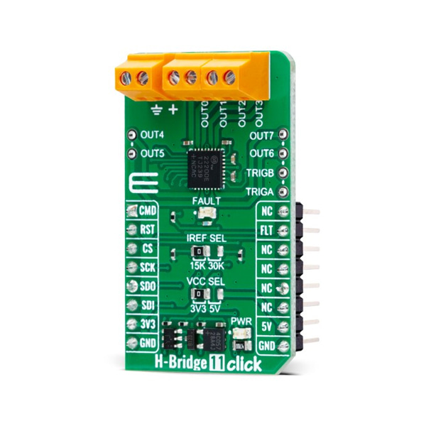
H-Bridge 11 Click is based on the MAX22200, an octal serial-controlled solenoid and motor driver from Analog Devices. The MAX22200 is rated for an operating voltage range from 4.5V to 36V, which can be brought externally through a VIN screw terminal. Each channel, market with OUTx, can be configured as a low-side or high-side driver and features a low-impedance with 200mΩ typical ON-resistance push-pull output stage with sink-and-source driving capability and up to 1A RMS driving current. Also, pairs of half-bridges can be paralleled to double the driving current or can be configured as full-bridges to drive up to four latched valves (bistable valves) or four brushed DC motors.
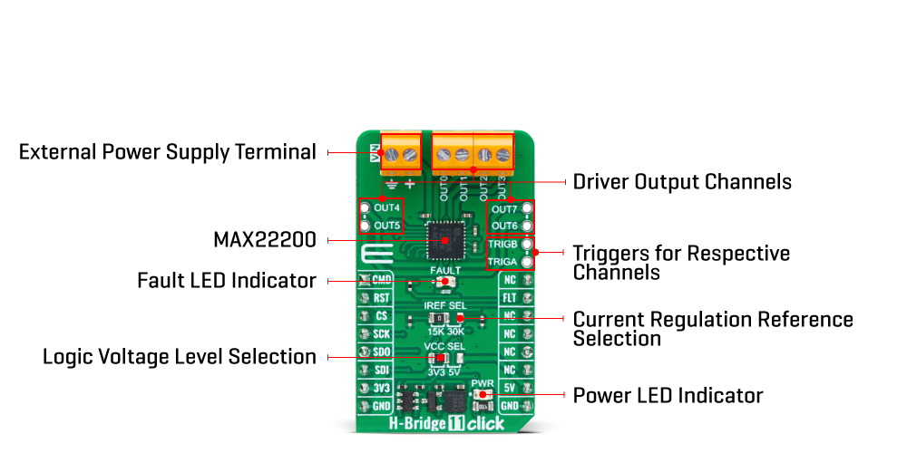
The MAX22200 features a two-level drive sequence for optimal control of solenoid valves such as voltage-drive (VDR) and current-drive regulation (CDR) (low-side driver only). In VDR mode, the MAX22200 outputs a PWM voltage with a programmable duty cycle through the SPI interface. The output current is proportional to the programmed duty cycle for a given supply voltage and solenoid resistor. In CDR mode, an internal integrated lossless current sensing (ICS) circuit senses the output current and compares it with a programmable reference current. The CDR loop modifies the PWM duty cycle so that the output current peak matches the programmed reference current. Reference current can be set using the IREF SEL jumper, providing the possibility of setting a current of 1A, 0.5A, or 0.25A depending on the position of the jumper and the set HFS bit (jumper at position 15k with HFS_bit=0 provides 1A, jumper at position 30k with HFS_bit=1 provides 0.25A).
This Click board™ communicates with MCU through a standard SPI interface, supporting clock speed up to 5MHz and the most common SPI mode, SPI Mode 0. It also can be enabled or disabled through the RST pin of the mikroBUS™ socket, hence, offering a switch operation to turn ON/OFF power delivery to the MAX22200. Depending on the content of the TRGnSPI bit in the configuration register of that specific channel, the driver channels can be activated/deactivated either using the SPI interface or through a logic input signal on unpopulated header pins TRIGA and TRIGB (0, 2, 4, 6 can be triggered by the logic input TRIGA, while 1, 3, 5, 7 can be triggered by using the logic input TRIGB). For a successful register write/read function, it is first necessary to set the CMD pin of the mikroBUS™ socket to an appropriate logic level: high for the write and low for the read command.
It also provides a fault status indication signal, routed to the FLT pin of the mikroBUS™ socket, alongside its red LED indicator marked as FAULT to indicate different fault conditions such as overcurrent protection, thermal shutdown, undervoltage lockout, open-load detection, and detection of plunger movement.
This Click board™ can operate with either 3.3V or 5V logic voltage levels selected via the VCC SEL jumper. This way, both 3.3V and 5V capable MCUs can use the communication lines properly. However, the Click board™ comes equipped with a library containing easy-to-use functions and an example code that can be used, as a reference, for further development.
SPECIFICATIONS
Type Brushed Applications Can be used for solenoid driver applications (valve control, relays control) in which low power consumption and a high level of integration are required On-board modules MAX22200 - serial-controlled solenoid and motor driver from Analog Devices Key Features Eight half-bridges up to +36V, high performance, programmable output current, two control methods, high flexibility, high-speed SPI interface, full set of protection and diagnostic features, and more Interface SPI Compatibility mikroBUS Click board size M (42.9 x 25.4 mm) Input Voltage 3.3V or 5V

