

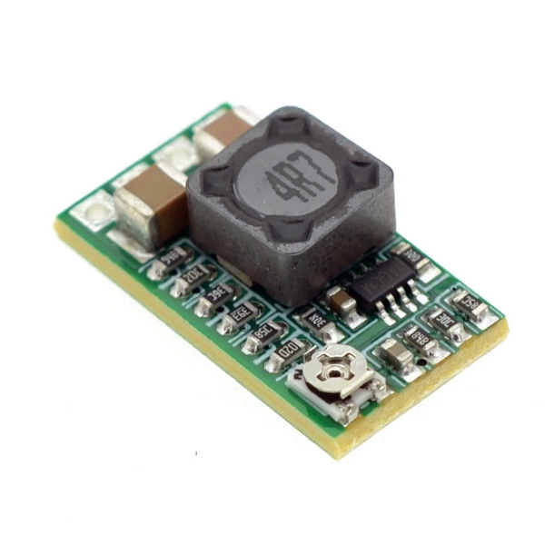
조절가능 DC-DC 스텝다운 컨버터 -1.8-12V 2A - MP2315
(DC-DC Converter Step-Down 1.8-12V 2A - MP2315)
개요
- 본 제품은 조절가능 DC-DC 스텝다운 컨버터 -1.8-12V 2A - MP2315입니다.
- MP2315 칩을 기반으로 디자인된 제품으로, 4.5V-24V를 입력 전압으로 받아 1V-22V까지 전압을 변환 하여 줄 수 있는 제품입니다.
- 연속적으로는 1.5A 출력을 피크시에는 2A 출력 전달이 가능하며, 보드상에 전압을 조절할 수 있는 포텐셔미터가 장착되어 있습니다.
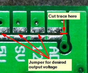
- 고정된 전압 출력을 사용하려면 ADJ 점퍼쪽 트레이스를 컷팅하고 원하는 전압의 솔더 점퍼를 연결하여 고정 출력 또한 얻을 수 가 있습니다.
특징
- Maximum Ratings
- VIN Input Voltage: 4.5-24V
- IO Maximum Output Current (peak): 2A
- Operating Ratings
- VO Output Voltage Range: 0.8-22V
- IO Output Current (max continuous): 1.5A
- Switching Frequency: 500kHz
- Output Ripple: 30mV
- Efficiency Varies depending on load: Up to 97.5%
- Electrical Isolation: Non-isolated
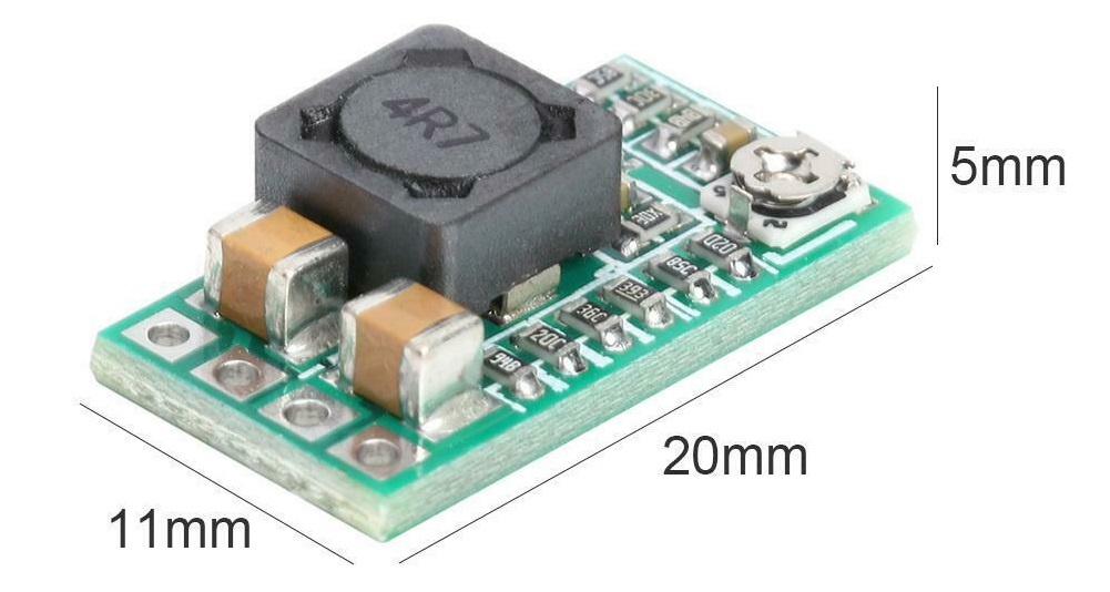
- Dimensions: 20x11x5mm
문서
-
Voltage Adjustment
- Using Adjustable Output
As-shipped, the module has a single-turn potentiometer for adjustment of the output voltage.
Turning the pot CW increases the output voltage while turning it CCW decreases the output voltage. Because the pot is single-turn, setting an exact voltage is typically not possible, but the setting can easily be set to within a couple percent of the target value which is fine for most applications. For example when targeting 5V, expect to hit 4.95 – 5.05V.
The lowest output voltage is approximately 0.8V. The upper limit of the adjustment range will depend on the input voltage and is typically about 0.6V less than the input voltage. With a 12V input for instance, the upper output limit will be approximately 11.4V.
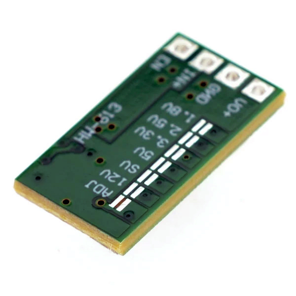
- Using Fixed Output
Optionally, a trace on the back of the module can be cut and one of several solder pads can be bridged to have the converter output a fixed voltage of 1.8V, 2.5V, 3.3V, 5V, 9V or 12V.MP2315 Mini Adjustable DC-DC Step-Down Module - Trace to Cut
Cutting the small trace requires a sharp Exacto knife or razor blade and either good eye-sight or a magnifier of some kind. Solder bridging the pads will require a soldering iron with a fairly small tip.
If it is desired to return to the adjustable output, the ADJ pads can be shorted.
In our testing, the accuracy of the fixed output voltages was within 5% on all settings and was very close on the 3.3 and 5V settings as shown in the table below.
-
Output Enable
The module has an EN (Enable) pin which is active HIGH.
The module has this pin pulled high by default, so the module will always be enabled and the EN pin can be left unconnected if the module will always be enabled.
To use this feature, the input can be driven LOW by connecting it to a digital output pin on an MCU or it can be grounded via a switch to disable the output. The EN pin is compatible with 3.3 and 5V logic levels.
Module Connections
These are very compact boards with 4 solder connections on standard 0.1″ centers. A male header strip is provided which can be soldered to the board for making connections.
1x4 Header
- EN = Enable. Active HIGH and pulled HIGH on the module. Pull LOW to disable the module output.
- IN+ = Input voltage
- GND = Ground
- VO+ = Output voltage
Keep in mind when using these modules on a solderless breadboard that with higher currents the voltage drop through standard breadboard jumpers can become significant. Ensure you use larger gauge wire, keep the wires short and/or double up on the wires to minimize any voltage drop.
NOTES
- Be sure to properly hook up the input and output connections before applying power to avoid possible damage to the module.
- Under higher current loads, the components can get fairly hot, so use care when handling

