

ATSAMD21G18 M0 WiFi 피더 보드 -ESP8285
(Challenger M0 WiFi)
개요
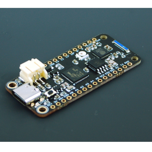
- 본 제품은 ATSAMD21G18 M0 WiFi 피더 보드 -ESP8285입니다.
- ATSAMD21G18 마이크로컨트롤러를 기반으로 디자인된 제품으로 ESP8285 WiFi 칩을 장착하고 있습니다.
- SAMD21 MCU는 256Kbyte의 플래쉬와 32Kbyte의 SRAM을 가지고 있으며, 외부 2MB 플래쉬 메모리를 지원합니다.
- USB C 커넥터를 장착하고 있습니다.
- 아두이노 개발환경에서 개발이 가능합니다.
특징
-
WiFi
To the Challenger M0 WiFi we also added an ESP8285 chip. For those of you that is unfamiliar with this device, it is basically an ESP8266 device with an integrated 1MByte of flash memory. This allows us to have an AT command interpreter inside this chip that the main controller can talk to and connect to you local WiFi network. The communications channel between the two devices is an unused UART on the main controller and the standard UART on the ESP8285. As simple as it can be.
The ESP8285 chip comes pre-flashed with Espressif's AT command interpreter stored in the internal 1MByte of the ESP8285. This interpreter support all of the operating and sleep modes of the standard ESP8266 framework which makes it easy to work with. Talking to the device is as easy as opening the second serial port (Serial2), resetting the ESP8285 and start listening for events and sending commands. To simplify this process we are also developing a library that is compatible with the standard ESP8266 environment.
USB Type C
In the recent years we have noticed that we are seeing more and more USB Type C cable laying around the lab due to the fact that all new phones and accessories use them. As of yet we haven't seen any shortage of micro USB cables but we are not getting any new ones any more and old ones do break occasionally. So we decided to go for a USB Type C connector for this board. A bonus of this is that they are quite bit more durable and you don't have to fiddle with the cable before plugging it in.
Challenger M0 WiFi Features
So, the board is packed with hardware features, here's a short list of its most prominent ones.
– Sturdy USB Type C connector
– ATSAMD21G18 @ 48MHz with 3.3V power
– 256KB FLASH + 32KB RAM
– 2 MByte of NOR FLASH memory
– 32.768 KHz crystal for clock generation & RTC
– 3.3V regulator with 600mA peak current output, most of which is reserved for the board itself
– USB native support, comes with UF2 USB bootloader
– 20 GPIO pins
– Hardware Serial, hardware I2C, hardware SPI support
– PWM outputs on all pins
– 6 x 12-bit analog inputs
– 1 x 10-bit analog ouput (DAC)
– Built in 250mA lipoly charger with charging status indicator LED
– Pin #13 red LED for general purpose blinking
– Power/enable pin
– 4 mounting holes
– Reset button
– ESP8285 WiFi chip with onboard antenna
– Neopixel LED that indicates board status but that can be used by the programmerChallenger M0 WiFi Software
The Challenger M0 WiFi board is 100% compatible with the Arduino framework. It has a unique board support package that fully supports all the features of the board. You can also install and run Circuitpython on the board if this is what you want to do. And while it is possible to run circuitpython or micropython on this board we do not recommend it. The RAM size is just not enough to be able to take advantage of the libraries available to control the WiFi chip on board. We have made available a UF2 image that you can use to try it out but we will not push this to the main Circuitpython repo.
Other
The boards comes with loose headers that can be soldered to the board if your application requires it.
문서
-
Arduino
Here's a short step by step instruction on how to install the Arduino board support package that you need to be able to access all the features of the board.
- Start your Arduino IDE (It needs to be 1.8.5 or higher)
- Select menu choice "File" and then "Preferences". You can also type Ctrl+comma (Ctrl-,) on your keyboard.
- Now add the URL "https://invector.se/files/package_ilabs_index.json" into the "Additional Boards Manager URLs" field.
- Click OK to close the preferences dialog.
- Now open the Boards Manager by selecting it in the "Tools->Board:" menu
- Scroll down until you see "Invector SAMD Boards" or search for Invector.
- Move your mouse to the box and click on install.
That is it, when the process is done you are ready to select the "Invector Labs Challenger M0 WiFi" board in the boards menu and start writing software for it.
Circuitpython/Micropython
While it is possible to run circuitpython or micropython on this board we do not recommend it. The RAM size is just not enough to be able to take advantage of the libraries available to control the WiFi chip on board. We have made available a UF2 image that you can use to try it out but we will not push this to the main Circuitpython repo.
You can download this test firmware here.
-
Arduino board package source files
Simple AT command library and example to get started using the Challenger with AT commands.
Hardware files
Espressif AT Command set
연관제품
- 연관제품 1

