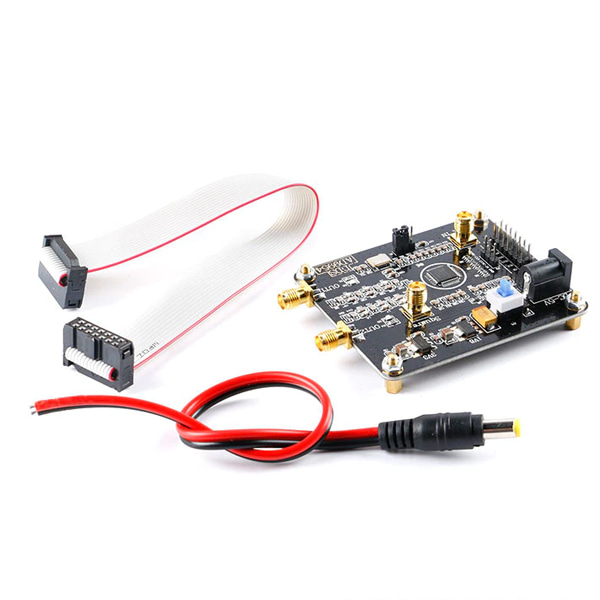
AD9954 DDS 모듈
(AD9954 DDS Module)
개요
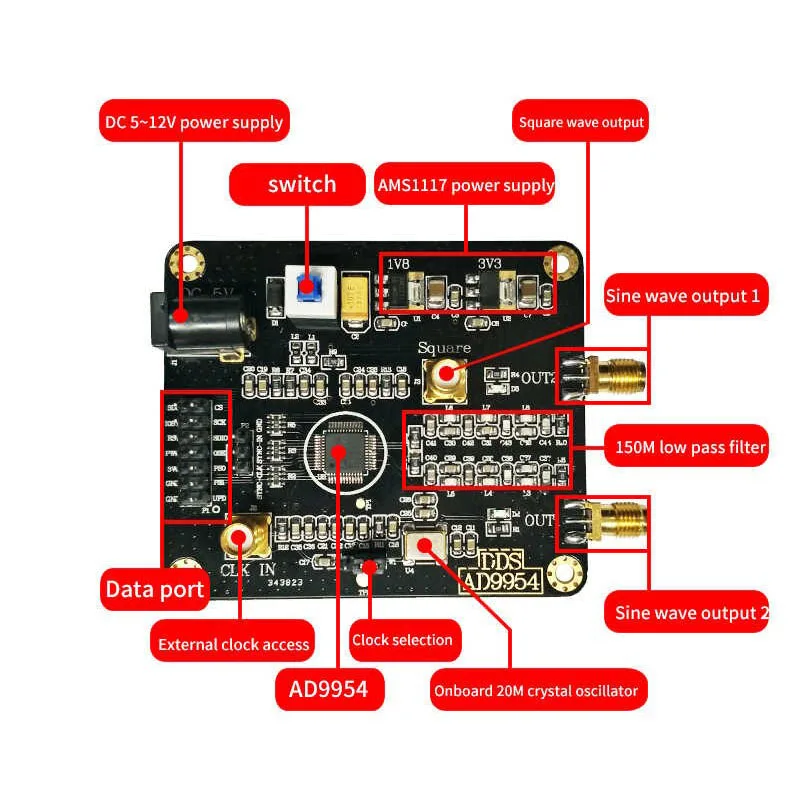
- 본 제품은 AD9954 DDS( direct digital frequency synthesizer) 모듈입니다.
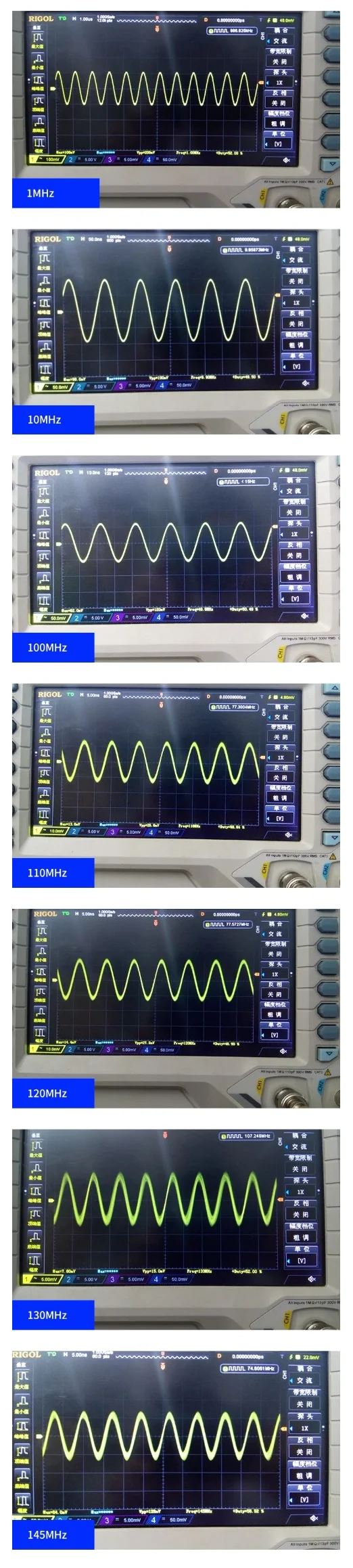
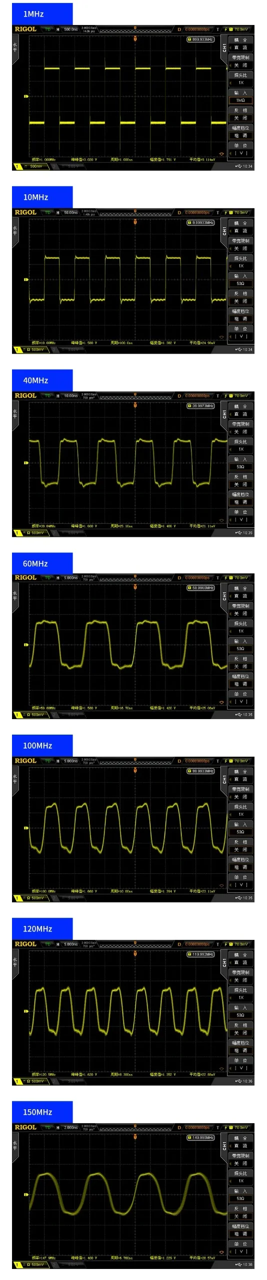
- 150Mhz까지의 Sine 파를 출력할 수 있습니다.
- 빠른 주파수 호핑과 정교한 주파수 튜닝(0.01Hz), phase harmonics (0.022 ° interval)이 가능합니다.
특징
-
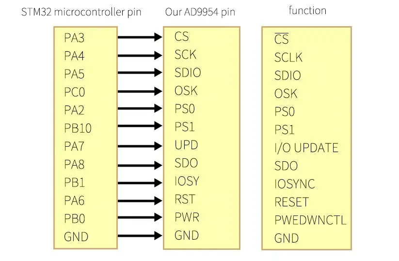
Module modelAD9954Module typedigital synthesis frequency sourcePower supply moduleDC-5VModule current100mA (MAX); quiescent current 48mA (TYPE) normal stick current 92mA (TYPE)Communication protocol moduleSPI serialModule offers routinesSTM32F103RCT6Routine platformSTM32F103X-M3 KEIL5 version source codeModule system main frequency400MHz (MAX)DAC resolution digits14 digitsPhase accumulator bits32 bitsModule output interfaceSMA; 24 hour salt spray anti-oxidationModule output signalssine wave, square wave; sine wave with 150MHz low-pass filter. Square shaft coupling output.Module output channel2 channel differential; phase difference is 180 degrees, high frequency output will have phase shift due to filterSignal characteristicsthe sine wave has no coupling output; the output has its own DC component. When you are connected to the radio frequency equipment, please add a DC block, or you can directly use an oscilloscope to measureHighest main frequency output sine signal range1Hz-140MHzMax main frequency output square wave signal range1Hz-120MHz 10MHz or more requires an oscilloscope input impedance of 50
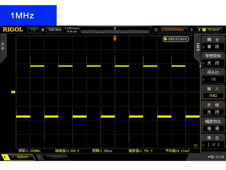
ohmsOutput amplitudesine wave 200mVpp (MAX) square wave 3.3 Vpp; sine wave amplitude decreases with increasing frequency, square wave waveform changes with increasing frequencyOutput impedance75 ohmsModule featuresseveral; high-performance DDS sine signal generator, high-order elliptical filter,
Low noise regulator chip, etc.Module applicationseveral; frequency signal generation, sine wave, square wave signal generation, sensor excitationModule specifications70 * 60 * 12; length * width * height-PCB sizeModule interface typeSMA signal output and external clock input, DC 5.5 socket XH 2.54 dual-row pin data interface
문서
-
Installation Instructions
Precautions for using the module:
(1) The module is a low-power consumption module, and the power supply does not exceed 5.5 V.
(2) Since the module is a high-precision device, in order to avoid unnecessary interference, it is recommended to use a linear power supply.
(3) It is recommended to use the SMA on BNC cable to directly observe the output signal for the output signal. Poor contact or poor quality wires can cause signal attenuation or excessive noise.
(4) The supplied code is only used for supporting main control board, and does not offer a microcontroller tutorial; additional functions have to be developed by yourself.
(5) If you simply need to test the function of the module, it is recommended to use the control board from our store. Power is supplied to the DDS module first, and then the power is supplied to the control board to generate a waveform. Long press the middle button to get the function.Details Images