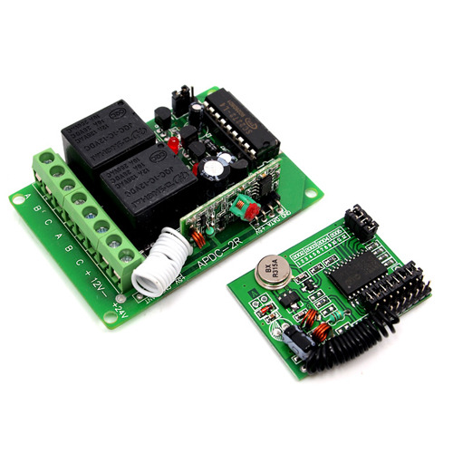
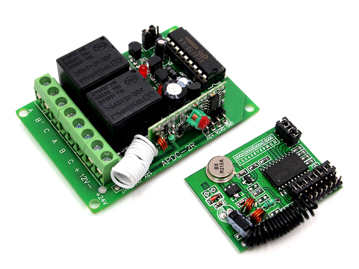
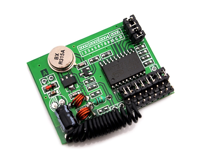
315Mhz 원격 2채널 릴레이 스위치 키트
(315Mhz remote relay switch kits
- 2 channels)
개요
- 본 제품은 원격 스위치로 전구, 팬, 조명 등의 12VDC 장치를 원격에서 제어할 수 있게 만들어 줍니다.
- 쉽게 사용이 가능하며 다양한 12V 어플리케이션에 사용이 될 수 있습니다.
특징
-
Basic Specification:
- Frequency: 315Mhz.
- Modulation: ASK
- Working voltage: 12VDC
- Receiver sensibility: -105dbm
- Emission distance: 100m in open ground
- Size: 68mm*47mm*12mm
-
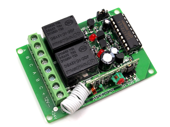
Pin Out:
Each Relay owns one group of 3 pins:A - Normally closed, open when relay activate
B - Common node
C - Normally open, close when relay activate
사용법
- Encoding and Decoding
The popular link is like this: MCU -> Encoder -> Transmitter ------ Receiver -> Decoder -> MCU,
PT2262(Encoder) and PT2272(Decoder) are optional, their existence is to 1)avoid confusing when multiple RF links in range 2) isolate disturbance. You can integrate the encoding and decoding work to the MCUs on both side. Whenever there is no 315Mhz devices around, you may use it as direct cable connection.
To setup a PT2272 and PT2262 link, you would need to set PT2262 by a little soldering: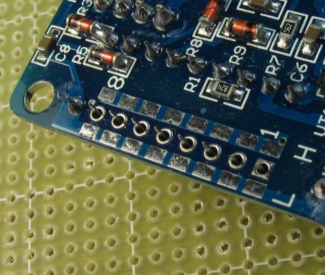
And setup the corresponding pins on PT2272: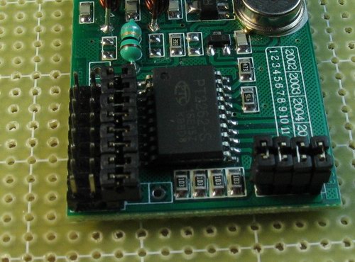
-
-
Relay Operation Modes:
The receiver has three modes that control how the relay outputs function. These modes are user selectable using the 3 pin jumper on the receiver.
Momentary:
Move the switch position to set the selected relay(s) in momentary mode. In momentary mode, the selected relay(s) will change its state and maintain it for the duration of the transmission received. Once the transmission is terminated, the relay will change back to its original state.
Flip-Flop:
Remove the shunt to set the selected relay(s) in Flip-Flop mode. In Flip-Flop mode, the selected relay(s) will change its state and maintain it until a matching transmission is received. Every time a transmission is received the relay will change its state and maintain it until another transmission is received.
Latching:
Move the switch position to set the selected relay(s) in Latching mode. In latching mode, when the selected relay is activated by the transmitter, that relay will change its state and maintain it until power to the receiver is removed or interrupted.
Please refer to the simple drawing for the 315Mhz RF link. On the transimitter side, You would need to supply 3-5VDC to the "+12V" pin,(Caution: the 12v is an error silk screen on PCB, never give it more than 5V), and set "TE" high(5V) to enable transmission. On the receiver side, you may use +5VDC(aka VCC) for power and read the output from D0~D3. "TV" will indicate thenever there is changed data incoming.