아두캠 미니 5M 픽셀 카메라 모듈 -OV5642
(ArduCAM Mini 5M Pixel Camera Module -OV5642)
개요
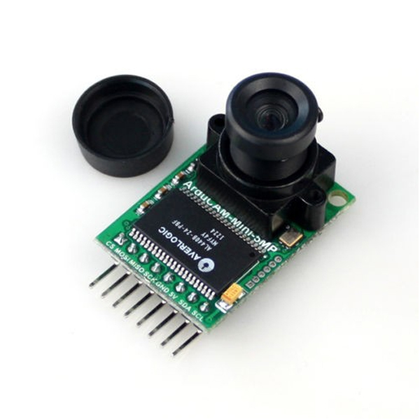
- 본 제품은 ArduCAM 미니 5메가 픽셀 카메라 모듈입니다.
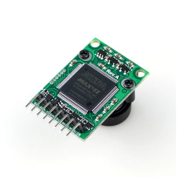
- ArduCAM Shield를 컴팩트하게 최적화 시킨 버전으로 HD 5M 픽셀 SPI 카메라입니다.
- SPI 인터페이스를 사용하기 때문에 카메라 인터페이스의 복잡성을 줄여 줄 수 있습니다.
- OV5642 5메가 픽셀 CMOS 이미지 센서가 장착되어 있으며 사용하기 쉬운 하드웨어 인터페이스, 오픈소스 코드 라이브러리를 지원합니다.
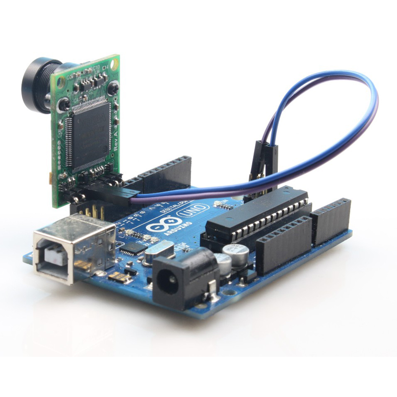
- 본 제품은 아두이노, 라즈베리파이, Chipkit, 비글본 블랙 등 SPI 및 I2C 인터페이스를 가진 플랫폼 어디에서든 사용이 가능합니다.
- 아두이노와 같은 로우 엔드급의 마이크로컨트롤러에서도 사용이 가능할 뿐아니라 여러 카메라 모듈을 하나의 마이크로컨트롤러에 연결하여 사용할 수 도 있습니다.
특징
- 5MP image sensor OV5642
- M12 mount or CS mount lens holder with changeable lens options
- IR sensitive with proper lens combination
- I2C interface for the sensor configuration
- SPI interface for camera commands and data stream
- All IO ports are 5V/3.3V tolerant
- Support JPEG compression mode, single and multiple shoot mode, one time capture multiple read operation, burst read operation, low power mode and etc.
- Well mated with standard Arduino boards
- Provide open source code library for Arduino, STM32, Chipkit, Raspberry Pi, BeagleBone Black
- Small form of factor
-
Key Specification
Key Specification 2MP 5MP Image Sensor OV2640 OV5642 Active array size 1600×1200 2592×1944 Shutter rolling shutter rolling shutter Lens 1/4 inch 1/4 inch SPI speed 8MHz 8MHz Frame buffer Size 384KB 512KB Board Size 34 x 24 mm 34 x 24 mm Weight 20g 25g Temperature -10℃~+55℃ -10℃~+55℃ Power Consumption Normal :5V/70mALow power mode: 5V/20mA Normal :5V/390mALow power mode: 5V/20mA Pin Definition
Table 1 ArduCAM Mini Pin Definition
Pin No. PIN NAME TYPE DESCRIPTION 1 CS Input SPI slave chip select input 2 MOSI Input SPI master output slave input 3 MISO Output SPI master input slave output 4 SCLK Input SPI serial clock 5 GND Ground Power ground 6 +5V POWER 5V Power supply 7 SDA Bi-directional Two-Wire Serial Interface Data I/O 8 SCL Input Two-Wire Serial Interface Clock -
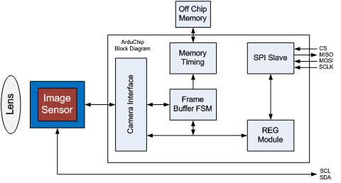
Block Diagram
Figure 2 shows the block diagram of ArduCAM mini shield which is composed by lens, image sensor and an ArduChip. The lens is changeable and can be mounted by S-mount (M12x0.5) or CS-mount lens holder. The ArduChip uses ArduCAM proprietary third generation camera controller technology which handles the complex camera, memory and user interface hardware timing and provides a user friendly SPI interface.
Functions
- Single Capture Mode
Single capture mode is the default capture mode of the camera. After issuing a capture command via SPI port, the ArduCAM will wait for a new frame and buffer the one entire image data to the frame buffer, and then assert the completion flag bit in the register. User only needs to poll the flag bit from the register to check out if the capture is done.
- Multiple Capture Mode
Multiple capture mode is advanced capture mode. By setting the number of frames in the capture register, the ArduCAM will capture consequent frames after issuing capture command. Note that number of frames should be set properly and make sure do not exceed the maximum memory space.
- JPEG Compression
The JPEG compression function is implemented in the image sensor. With proper register settings to the sensor, user can get different resolution with JPEG image stream output. It is recommended to use JPEG output to get higher resolution than RGB mode, due to the limitation of frame buffer.
- Normal Read and Burst Read Operation
Normal read operation reads each image data by sending a read command in one SPI read operation cycle. While burst read operation only need to send a read command then read multiple image data in one SPI read operation cycle. It is recommended to use burst read operation to get better throughput performance.
- Rewind Read Operation
Sometimes user wants to read the same frame of image data multiple times for processing, the rewind read operation is designed for this purpose. By resetting the read pointer to the beginning of the image data, user can read the same image data from the start point again.
- Low Power Mode
Some battery power device need save power when in the idle status, the ArduCAM offers the low power mode to reduce power consumption, by shutdown the sensor and memory circuits.
- Image Sensor Control
Image sensor control function is implemented in the image sensor. By setting proper set of register settings, user can control the exposure, white balance, brightness, contrast, color saturation and etc.

문서
연관제품
- 연관제품 1