LGT8F328P 아두이노 프로 미니 -ATMEGA328P 호환보드
(LGT8F328P Arduino Pro Mini -ATMEGA328P Compatible)
개요
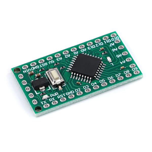
- 본 제품은 LGT8F328P 아두이노 프로 미니 -ATMEGA328P 호환보드입니다.
- ATMEGA328P 호환 MCU인 LGT8F328P 칩을 탑재하여 디자인된 제품입니다.
- 아두이노 프로 미니와 호환됩니다.
특징
- The LGT8F328P SSOP20 development board is intended to be a very low cost alternative to embedded Arduino boards such as the Pro Mini . Instead of using the Nanos ATMega328p, it instead features the LG8F328P microcontroller. This microntroller was not only designed to be a low cost replacement for the ATMega328 but it also significantly improves on the 328s features. Most significant of which, the LG8F328P is capable of running sketches at over twice the speed of the Nano and includes other improvements such as higher resolution ADCs, a DAC, and built in unique serial number (GUID).
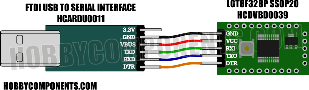
- PLEASE NOTE: To program this board via the Arduino IDE you will need a suitable USB to 5V TTL serial adaptor. Please see the following items:
문서
- Arduino IDE Setup Guide:
Note: This setup guide assumes that you have already downloaded and installed the Arduino IDE. If not please download and install it from the Arduino website here: https://www.arduino.cc/en/software
Adding support for the LGT8F328P development board is as easy as adding support for most other types of Arduino boards thanks to a set of board manager files created by David Buezas. To add board support to your Arduino IDE simply follow these steps:
1) Open up your Arduino IDE and click on the 'File' menu then select 'Preferences'
2) In the window that opens up locate the text box labelled 'Additional Boards Manager URLs:' then click on the open window button to the right of the text box:
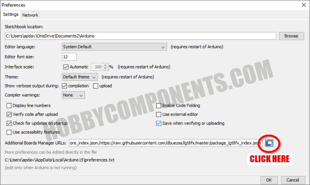
3) In the window that opens up cut and paste the following on a new line:
https://raw.githubusercontent.com/dbuez ... index.json
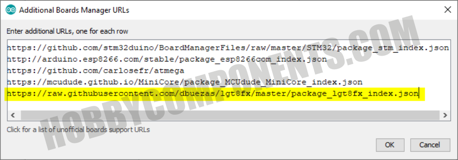
4) Once pasted in, close the window and the Preferences window by clicking the OK buttons.
5) Next, in the main Arduino IDE window click the 'Tools' menu then go to the 'Board:' option and select 'Boards Manager' from the sub-menu.
6) In the Boards manager window that opens up locate the board files titled 'LGT8fx Boards' and then click on it's install button.
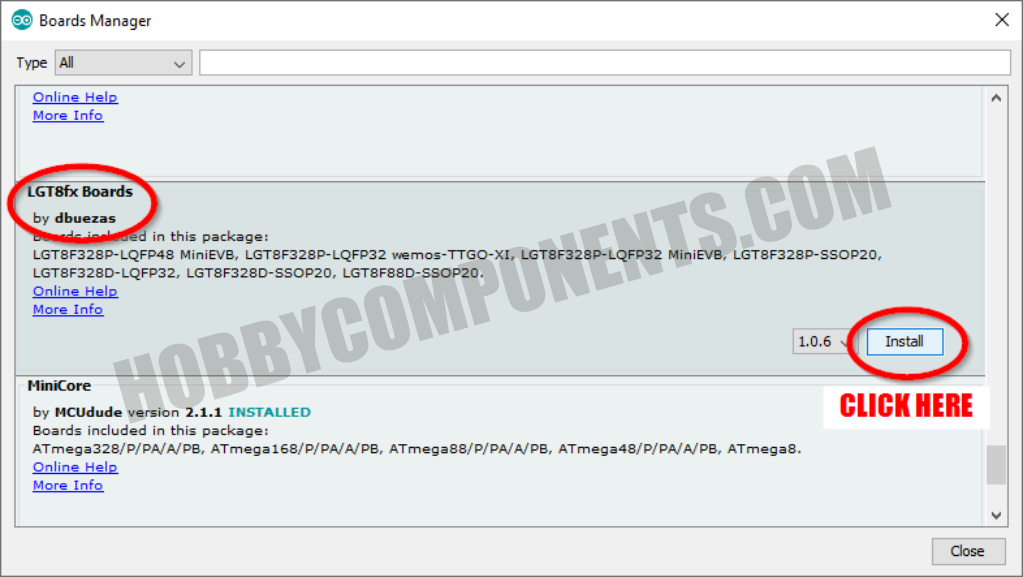
7) The Arduino IDE will now install the board files required to support the LG8F328P board:
Now plug the LGT8F328P development board into your computer via your USB to serial adaptor.
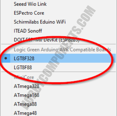
Open the Arduino IDE and click on the 'Tools' menu then under the 'Boards' menu you should find a few new board options for various LGTF328 based boards. Select the board named 'LGTF328'
Once selected set the other settings as follows:
Clock Source: "Internal"
Clock: "32 MHz"
Variant: "328P-SSOP20 (e.g. green pseudo pro mini)"
Port: The COM port assigned to your USB to serial adaptor
You are now ready to upload a sketch to your board. To check that everything is set up correctly try uploading the following blink sketch:
-
void setup()
-
{
-
pinMode(13, OUTPUT);
-
}
-
-
void loop()
-
{
-
digitalWrite(13, HIGH);
-
delay(1000);
-
digitalWrite(13, LOW);
-
delay(1000);
-
}
GeSHi © Codebox Plus Extension
If everything was setup correctly the sketch should upload to your board and when complete its built-in LED should be blinking slowly
FAQ:
How do I use the DAC?
The DAC is available on pin D3. You can use it via the Arduinos analogWrite() function except rather than outputting a PWM signal it will instead output an 8 bit resolution analogue voltage. See example sketch:
-
// Output a sawtooth waveform as fast as possible. (c) HobbyComponents.com
-
-
byte level = 0;
-
-
void setup()
-
{
-
analogReference(DEFAULT);
-
-
pinMode(DAC0, ANALOG); //DAC0 is pin D3
-
}
-
-
void loop()
-
{
-
analogWrite(DAC0, level);
-
level++;
-
}
GeSHi © Codebox Plus Extension
How do I access the built-in serial number?
The 32 bit serial number is accessed via 8 bit registers GUID0, GUID1, GUID2, & GUID3. You can access these as one 32 bit number like this:
-
// Access the devices unique serial number (c) HobbyComponents.com
-
void setup()
-
{
-
Serial.begin(9600);
-
-
// Assign a 32 bit pointer to the start of the serial number
-
uint32_t *guid = (uint32_t) &GUID0;
-
-
// Output the serial number to the UART
-
Serial.println(*guid, HEX);
-
}
-
-
-
void loop()
-
{
-
}
GeSHi © Codebox Plus Extension
-
연관제품
- 연관제품 1