UART - I2C 변환 모듈 -SC18IM704
(UART TO I2C CLICK)
개요
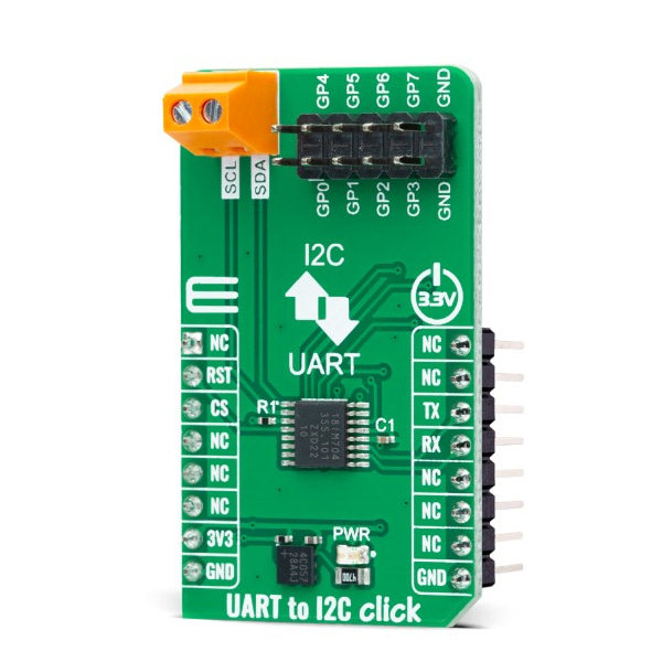
- 본 제품은 UART - I2C 변환 모듈 -SC18IM704 입니다.
- UART 호스트 인터페이스와 시리얼 I2C 인터페이스간 프로토콜 변환을 하여 주는 제품으로 SC18IM704 을 기반으로 디자인되었습니다.
- MCU는 모듈과 UART를 통해 ASCII 명령어로 통신하여 I2C 버스를 제어합니다.
- 3.3V 시스템과 사용이 가능합니다.
특징
-
HOW DOES IT WORK?
UART to I2C Click is based on the SC18IM704, a bridge between the standard UART port and a serial I2C bus from NXP Semiconductors. The SC18IM704 consists of a full-functional advanced UART interface that communicates with the host MCU through the commonly-used RX and TX pins of the mikroBUS™ socket. It is also characterized by a high baud rate of up to 460.8 kbit/s and 256-byte FIFO for the transfer/receive data process. The serial data format is fixed to a one start bit, 8 data bits, and one stop bit. After the reset feature, the baud rate defaults to 9600 bit/s and can be changed through the Baud Rate Generator (BRG) registers.
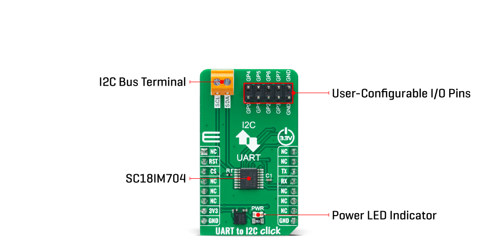
After a Power-Up sequence or already-mentioned hardware reset, achievable through the RST pin of the mikroBUS™ socket, the SC18IM704 will send two continuous bytes to the host MCU to indicate a Start-Up condition. These two continuous bytes are 0x4F and 0x4B, representing an 'OK' state in the ASCII messages protocol. After the correct initial sequence, direct communication is enabled with other I2C-bus devices connected to the populated I2C-bus terminal. The I2C bus uses two wires (SCL and SDA) to transfer information between connected devices, providing a byte-oriented interface that supports data transfers up to 400kHz.
The SC18IM704 can also be placed in a software-configurable low-power mode (Power-Down mode). Upon entering the Power-Down state, the UART RX pin is used to exit Deep Power-down mode. The bridge remains in the Deep Power-down mode as long as the RX pin remains in a high logic state. Any character sent brings the bridge out of Deep Power-down mode but ignores the character. In addition to all these features, the SC18IM704 has several general-purpose I/O pins on the populated header with labeled GP pins. These pins have the option of software setting their function as push-pull, open-drain, or input-only.
This Click board™ can be operated only with a 3.3V logic voltage level. The board must perform appropriate logic voltage level conversion before using MCUs with different logic levels. However, the Click board™ comes equipped with a library containing functions and an example code that can be used as a reference for further development.
SPECIFICATIONS
Type I2C Applications Can be used for industrial applications such as communication bridges, process and automation control, I2C bus support, and more On-board modules SC18IM704 - bridge between UART port and a serial I2C bus from NXP Semiconductors Key Features High speed UART host interface, programmable I/O pins, 256-byte TX/RX FIFO, programmable baud rate, Power-down mode, UART ASCII messages protocol, Reset, and more Interface UART Compatibility mikroBUS Click board size M (42.9 x 25.4 mm) Input Voltage 3.3V