Xbee3 지그비 모듈 -XB3-24Z8UM
(XBEE 2 CLICK)
개요
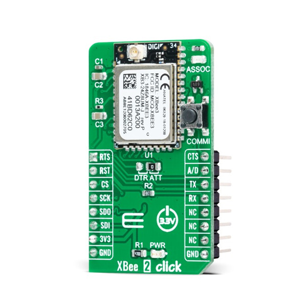
- 본 제품은 Xbee3 지그비 모듈 -XB3-24Z8UM 입니다.
- Digi XBee® 3 transceiver XB3-24Z8UM 을 기반으로 디자인된 제품입니다.
- 여러 주파수와 무선 프로토콜들(Zigbee, 802.15.4, DigiMesh® and BLE) 간 스위치를 할 수 있는 유연성을 지원합니다.
- SPI,UART 인터페이스를 지원하며, 3.3V 시스템과 사용이 가능합니다.
특징
-
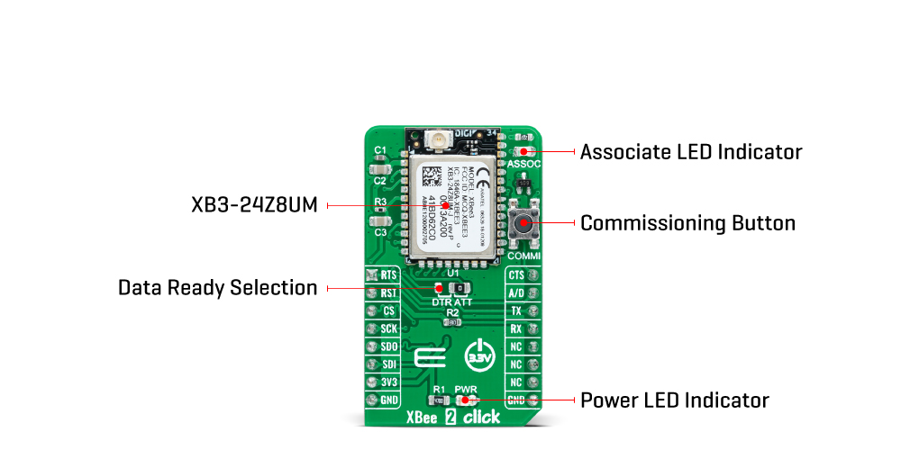
Xbee 2 Click as its foundation uses the XB3-24Z8UM, a Digi XBee® 3 Zigbee 3.0 transceiver module providing wireless end-point connectivity from Digi International. This module uses the IEEE 802.15.4 networking protocol for fast point-to-multipoint or peer-to-peer networking designed for high-throughput applications requiring low latency and predictable communication timing. Building on industry-leading technology, the pre-certified XB3-24Z8UM module delivers the flexibility to switch between multiple frequencies and wireless protocols as needed (Zigbee, 802.15.4, DigiMesh®, and BLE), offering a fully interoperable ecosystem covering all vertical markets.
This Click board™ comes with a configurable host interface allowing communication with MCU using the chosen interface. The XB3-24Z8UM can communicate with MCU using the UART interface with commonly used UART RX, TX, and hardware flow control pins UART CTS and RTS (Clear to Send and Ready to Send), or using the SPI interface (XBee module will work as an SPI-slave only). In the case of the SPI interface, the users can use it to configure the module and write the library by themselves. The XB3-24Z8UM also has built-in Digi TrustFence® security, identity, and data privacy features, employing more than 175 controls to protect against new and evolving cyber threats.
The Xbee 2 Click is associated with many other features, such as the reset function and the possibility of visual and digital indicators. An active-low reset signal routed on the RST pin of the mikroBUS™ socket activates a hardware reset of the system, while a yellow LED indicator marked as ASSOC represents a visual indication of the module's connection to the network. If the LED is constantly on, it means that the module is not connected to the mobile network, while the case of standard flashing of the LED represents the normal operating mode.
The A/D pin routed on the INT pin of the mikroBUS™ socket represents a type of interrupt whose function can be selected by positioning an onboard SMD jumper to an appropriate position labeled as DTR or ATT. DTR position is a "Data terminal ready" function used to tell the XBee module that the host MCU is ready to communicate, while the ATT position (SPI Attention) represents an indicator for the SPI interface whenever the Xbee module has data for the host MCU. In addition, the board also has a commissioning pushbutton marked as COMMI which, combined with an ASSOC LED, provides various simple functions to aid in deploying devices in a network.
This Click board™ can be operated only with a 3.3V logic voltage level. The board must perform appropriate logic voltage level conversion before using MCUs with different logic levels. However, the Click board™ comes equipped with a library containing functions and an example code that can be used, as a reference, for further development.
SPECIFICATIONS
Type ZigBee Applications Can be used for broad smart-energy applications, wireless alarms and security, building automation, and others On-board modules XB3-24Z8UM - Digi XBee® 3 Zigbee 3.0 radio module providing wireless end-point connectivity from Digi International Key Features Industry-leading technology, pre-certified, flexibility, multiple frequencies and wireless protocols, security features, high programmability, and more Interface SPI,UART Compatibility mikroBUS Click board size M (42.9 x 25.4 mm) Supply Voltage 3.3V
문서
연관제품
- 연관제품 1