2상 바이폴라 스텝모터 드라이버 -TB9120AFTG
(STEPPER 11 CLICK)
개요
- 본 제품은 2상 바이폴라 스텝모터 드라이버 -TB9120AFTG 입니다.
- 2상 바이폴라 스텝모터 드라이버 TB9120AFTG 칩을 탑재하고 있습니다.
- 풀스텝에서 1/32 스텝까지 지원합니다.
- I2C 인터페이스를 가지고 있으며, 3.3V/5V 시스템과 사용이 가능합니다.
특징
-
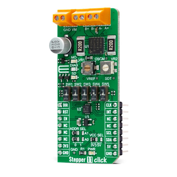
Stepper 11 Click as its foundation uses the TB9120AFTG, a constant-current 2-phase stepping motor driver for automotive applications from Toshiba Semiconductor. The TB9120AFTG incorporates low on-resistance DMOS FETs, which can deliver a 2A maximum current. A built-in mixed decay mode helps to stabilize the current waveforms. Numerous protection mechanisms are also incorporated, such as over-current and over-temperature detection, thermal shutdown, and stall detection.
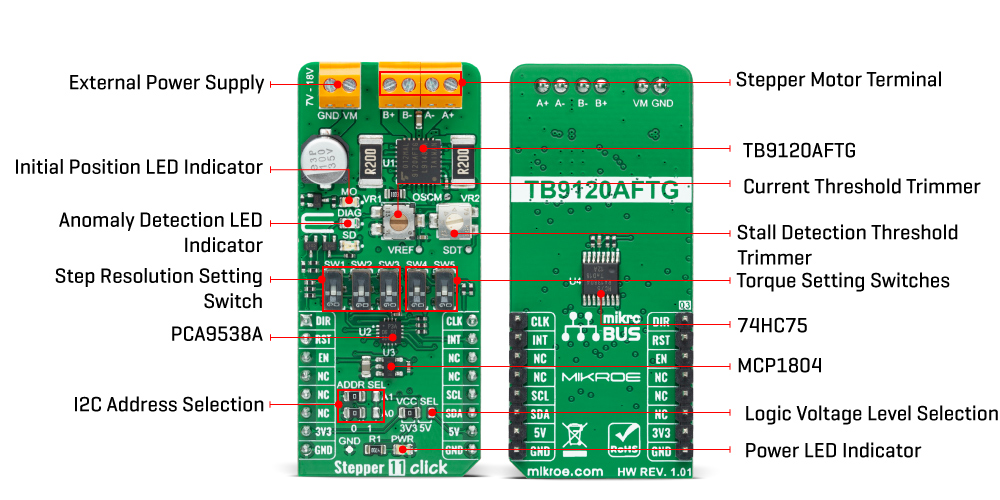
Thanks to the large number of micro-steps they support, motor noise can be significantly reduced with smoother operation and more precise control. It is suited to a wide range of general automotive applications using stepping motors and supports an operational temperature range covering -40°C to 125°C. The current value is set by the reference voltage value obtained by the MCP1804, a low-dropout voltage regulator. The current threshold point for the VREF pin of the TB9120AFTG, alongside MCP1804, can be set manually using an onboard trimmer labeled as VR1.
Alongside I2C communication, several GPIO pins connected to the mikroBUS™ socket pins are also used to forward the information to the MCU, associated with the PCA9538A port expander with a maximum frequency of 400kHz. The PCA9538A also allows the choice of the least significant bit (LSB) of its I2C slave address by positioning SMD jumpers labeled as ADDR SEL to an appropriate position marked as 0 and 1.
The Enable pin, labeled as EN and routed to the CS pin of the mikroBUS™ socket, optimizes power consumption and is used for power ON/OFF purposes. All circuits, including the interface pins, are inactive in this state, and the TB9120AFTG is in the form of minimum power consumption. A simple DIR pin routed to the AN pin on the mikroBUS™ socket allows MCU to manage the direction of the stepper motor (clockwise or counterclockwise). At the same time, the onboard switches labeled from SW1-SW3 enable users to set the excitation mode, stepper motor step resolution, and SW4-SW5 sets torque, rotational force.
In addition to these features, this Click board™ also uses the CLK step clock pin, routed to the PWM pin of the mikroBUS™ socket, for PWM constant-current control, allowing stable output waveforms in mixed decay mode. The RST pin of the mikroBUS™ socket initializes an electrical angle in the internal counter to set an initial position. Achieving an initial position is indicated via onboard blue LED labeled as MO.
This Click board™ also has two additional LEDs for anomaly indication. Suppose a state such as a motor load open, overtemperature, or overcurrent is detected. In that case, such anomaly is indicated by a red LED marked as DIAG, while an orange LED labeled as SD indicates when a stall (step-out) situation is detected. Motor-stall detection threshold can also be set manually using an onboard trimmer labeled as VR2.
The Stepper 11 Click supports an external power supply for the TB9120AFTG, which can be connected to the input terminal labeled as VM and should be within the range of 7V to 18V, while the stepper motor coils can be connected to the terminals labeled as B+, B-, A-, and A+.
This Click board™ can operate with both 3.3V and 5V logic voltage levels selected via the VCC SEL jumper. This way, it is allowed for both 3.3V and 5V capable MCUs to use communication lines properly. However, the Click board™ comes equipped with a library containing easy-to-use functions and an example code that can be used, as a reference, for further development.
-
Type Stepper Applications Can be used for a small stepping motors in a wide range of automotive applications On-board modules TB9120AFTG - constant-current 2-phase stepping motor driver for automotive applications from Toshiba Semiconductor Key Features PWM constant-current control, built-in a mixed decay mode, selectable excitation mode, anomaly detection functions, stall detection function, and many more Interface GPIO,I2C Compatibility mikroBUS Click board size L (57.15 x 25.4 mm) Input Voltage 3.3V or 5V,External