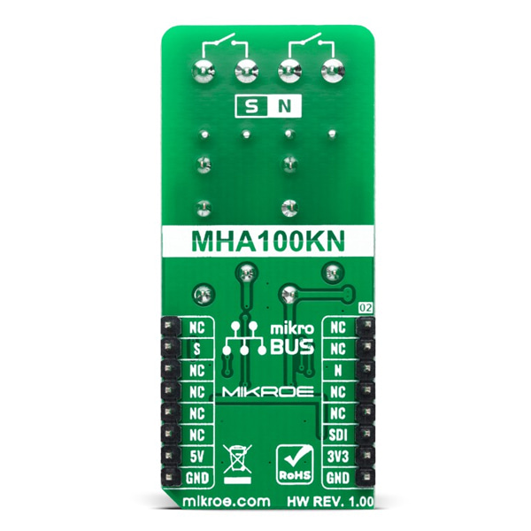
홀 센서 스위칭 2채널 릴레이 -MHA100KN
(HALL SWITCH 2 CLICK)
개요
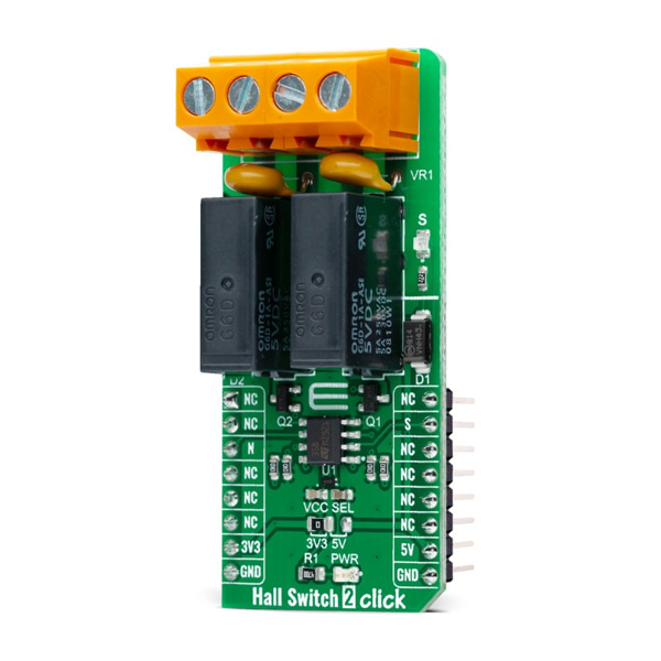
- 본 제품은 홀 센서 스위칭 2채널 릴레이 -MHA100KN 입니다.
- MHA100KN 홀센서와 2개의 릴레이를 탑재한 제품입니다.
- 자석과 같이 동작하여 자석의 근접 유무에 따라 릴레이를 동작시킵니다.
- 3.3V/5V 시스템과 사용이 가능합니다.
특징
-
Type Magnetic Applications Can be used for various applications activated by the magnetic field, such as contactless switches, lids or tray position detecting switches, or other similar applications that require contactless switching of the relay contacts On-board modules MHA100KN - high-performance, low-power Hall-Effect sensor from MEMSIC Key Features Low power consumption, reliable contactless switching by the magnetic field, separate sensors for both south and north pole magnetic fields, high-quality compact relays, and more Interface GPIO Compatibility mikroBUS Click board size L (57.15 x 25.4 mm) Input Voltage 3.3V or 5V -
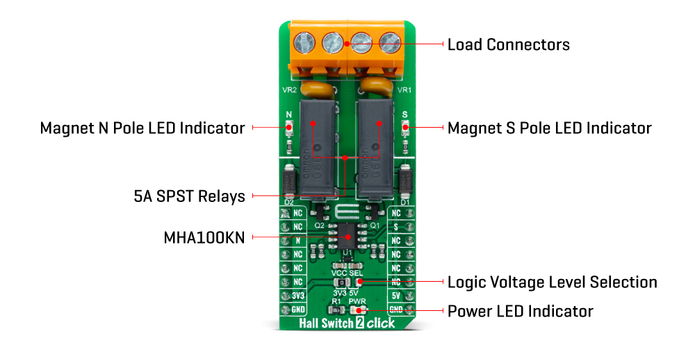
Hall Switch 2 Click as its foundation uses the MHA100KN, a high-performance, low-power Hall-Effect sensor from MEMSIC. This Click board™ detects the presence and magnitude of a magnetic field using the Hall effect. It consists of two high-quality relays, which the MHA100KN activates. When the north pole magnetic field is introduced to the sensor, one of the relays will be activated; otherwise, the other relay will be activated.
The outputs of the MHA100KN are routed to the LM358 operational amplifier, which works as the inverting comparators. When the output of the MHA100KN is activated, pulled to a low logic level, the output from the comparator will be set to 5V, which will cause biasing of the BJTs, allowing current flow through the relay coil and thus forming a magnetic field necessary for closing the relay contacts. A Schottky diode across the relay coils prevents the reverse kickback voltage, which forms due to the inert nature of the coils.
Hall Switch 2 Click communicates with MCU using two GPIO pins labeled S and N. The north pole output is routed to the CS pin, while the south pole output is routed to the INT pin of the mikroBUS™ socket so that the MCU can monitor the status of the MHA100KN. Activation of the relay coils is also visually indicated by the yellow and red LEDs, respectively.
Two varistors VR1 and VR2, are used to prevent voltage peaks when the load is connected or disconnected on the relay output contacts. However, the relays allow up to 5A for 250VAC / 30VDC, so the connected load should not exceed these power r0atings.
This Click board™ can operate with both 3.3V and 5V logic voltage levels selected via the VCC SEL jumper. This way, it allows both 3.3V and 5V capable MCUs to use the communication lines properly. However, the Click board™ comes equipped with a library containing easy-to-use functions and an example code that can be used, as a reference, for further development.