고속 CAN FD 트랜시버 -ATA6571
(ATA6571 CLICK)
개요
- 본 제품은 고속 CAN FD 트랜시버 -ATA6571 입니다.
- CAN프로토콜 컨트롤러와 인터페이스하여 사용할 수 있으며, 2선 CAN BUS에 연결할 수 있는 트랜시버 모듈입니다.
- UART 인터페이스를 가지고 있으며, 3.3V/5V 시스템과 사용이 가능합니다.
특징
-
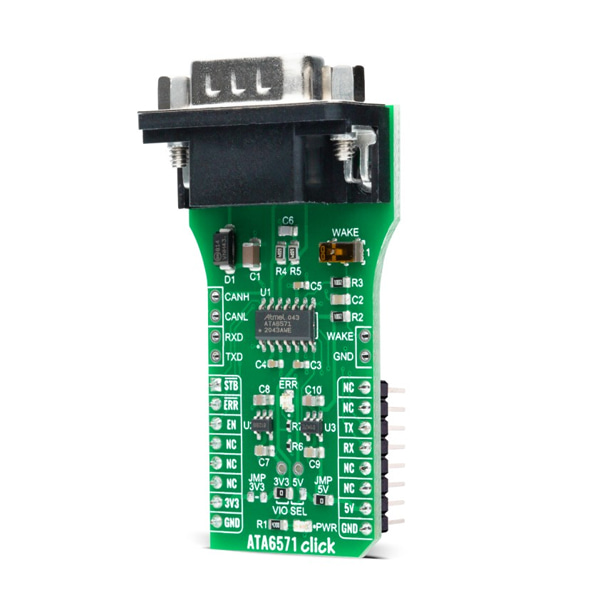
ATA6571 Click is based on the ATA6571, a standalone high-speed CAN FD transceiver up to 5 Mbit/s that interfaces a Controller Area Network (CAN) protocol controller and the physical two-wire CAN bus from Microchip. It offers improved Electromagnetic Compatibility (EMC) and ESD performance. Its advanced low-power management with local and remote Wake-Up support makes it possible to achieve low current consumption in Standby and Sleep mode, even when the internal I/O and transceiver supplies are switched off. The ATA6571 supports functional safety-related applications. Internal Safety Mechanisms prevent device malfunction due to undervoltage and overtemperature, detect bus dominant and recessive clamping, and prevent blocking of the CAN bus due to permanent dominant or recessive states of RXD and TXD.
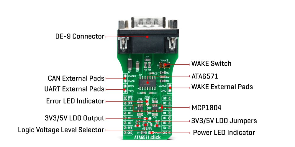
The ATA6571 has one pin used for waking up the device from Sleep mode. This pin is connected to an external switch labeled as WAKE to generate a local Wake-Up function. A Wake-Up event on the CAN bus switches the inhibit output pin INH to the High level. The INH pin provides an internal switch towards the battery supply voltage and control external voltage regulators, the MCP1804 from Microchip. Through SMD jumpers labeled as JMP3V3 and JMP5V, the LDOs output voltages can be used to power up the mikroBUS™ 3.3V and 5V power rails. However, it should be noted that Mikroe does not advise powering up their systems this way. That is why these jumpers are left unpopulated by default.
The ATA6571 communicates with MCU using the UART interface with the default baud rate of 9600 bps for the data transfer. In addition to UART communication pins from the mikroBUS™ socket, the user can connect the TX/RX signals directly through the UART External header on the left edge of the board. This Click board™ comes equipped with the standard DB-9 connector, making interfacing with the CAN bus simple and easy. Besides, the user can connect the CAN signals directly through the CAN External header, also on the left edge of the board.
In addition to these features, the ATA6571 also uses several GPIO pins connected to the mikroBUS™ socket. The EN pin routed on the CS pin of the mikroBUS™ is used for Enable Control. Together with the STB pin routed on the AN pin of the mikroBUS™ socket, which represents Standby Mode Control, the EN pin controls the operating mode of the device. It also provides a pull-down to force the transceiver into Recessive mode if EN is disconnected. Next to these pins, the ATA6571 uses another pin labeled as ERR routed on the RST pin of the mikroBUS™ used as Error Indication. This pin reflects the device status and can be visually displayed using the LED indicator labeled as ERR.
This Click board™ is designed to operate with both 3.3V and 5V logic voltage levels selected via the VIO SEL jumper. It allows for both 3.3V and 5V capable MCUs to use the UART communication lines properly. However, the Click board™ comes equipped with a library that contains easy to use functions and an example code that can be used, as a reference, for further development.
-
Type CAN Applications Can be used for all types of high-speed CAN networks, especially in nodes requiring low-power mode with wake-up capability via the CAN bus. On-board modules ATA6571 Click is based on the ATA6571, a standalone high-speed CAN FD transceiver up to 5 Mbit/s that interfaces a Controller Area Network (CAN) protocol controller and the physical two-wire CAN bus from Microchip. Key Features High-Speed CAN Transceiver, improved EMC Compatibility and ESD performance, very low power consumption, remote wake-up support, protection and diagnostic functions, and more. Interface UART Compatibility mikroBUS Click board size L (57.15 x 25.4 mm) Input Voltage 3.3V or 5V,External