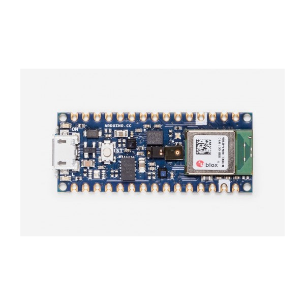
정품 아두이노 나노 33 BLE 센스 보드
-BT5.0, IMU, 온습도, 조도,컬러, 제스쳐, 마이크
(ARDUINO NANO 33 BLE SENSE)
개요
- 본 제품은 아두이노 나노 33 BLE 정품 보드입니다.
- Nordic nRF52840 프로세서와 NINA B306 모듈을 기반으로 디자인된 아두이노로 BLE 및 블루투스 5 프로토콜을 지원합니다.
- 아두이노 IDE 온라인/오프라인 개발환경에서 개발을 지원할 수 있으며, 9축 IMU 센서, 온도, 압력, 습도, 조도, 컬러, 제스쳐 센서 및 마이크로폰을 탑재하고 있습니다.
- 웨어러블 장치나 제스쳐 센싱이 필요한 프로젝트 등에 응용 할 수 있습니다.
특징
-
This board is based on the nRF 52840microcontroller.
Clock 64MHz Flash 1MB RAM 256KB Please note: Arduino Nano 33 BLE Sense only supports 3.3V I/Os and is NOT 5V tolerant so please make sure you are not directly connecting 5V signals to this board or it will be damaged. Also, as opposed to Arduino Nano boards that support 5V operation, the 5V pin does NOT supply voltage but is rather connected, through a jumper, to the USB power input.
To avoid such risk with existing projects, where you should be able to pull out a Nano and replace it with the new Nano 33 BLE Sense, we have the 5V pin on the header, positioned between RST and A7 that is not connected as default factory setting. This means that if you have a design that takes 5V from that pin, it won't work immediately, as a precaution we put in place to draw your attention to the 3.3V compliance on digital and analog inputs.
5V on that pin is available only when two conditions are met: you make a solder bridge on the two pads marked as VUSB and you power the NANO 33 IoT through the USB port. If you power the board from the VIN pin, you won't get any regulated 5V and therefore even if you do the solder bridge, nothing will come out of that 5V pin. The 3.3V, on the other hand, is always available and supports enough current to drive your sensors. Please make your designs so that sensors and actuators are driven with 3.3V and work with 3.3V digital IO levels. 5V is now an option for many modules and 3.3V is becoming the standard voltage for electronic ICs.
The Bluetooth is managed by a NINA B306 module.
The IMU is a LSM9DS1 and it is managed through I2C.
The LPS22HB reads barometric pressure and environmental temperature.
The HTS221 senses relative humidity.
The APDS-9960 is a digital proximity, ambient light, RGB and gesture sensor.
The MP34DT05 is the digital microphone
The board has a two 15 pins connectors - one on each side -, pin to pin compatible with the original Arduino Nano.
Pin Funcion Type Description 1 D13/SCK Digital SPI SCK; GPIO 2 +3V3 Power Out Internally generated power output to external devices 3 AREF Analog Analog Reference; can be used as GPIO 4 A0 Analog ADC in; can be used as GPIO 5 A1 Analog ADC in; can be used as GPIO 6 A2 Analog ADC in; can be used as GPIO 7 A3 Analog ADC in; can be used as GPIO 8 A4/SDA Analog ADC in; I2C SDA; Can be used as GPIO (*) 9 A5/SCL Analog ADC in; I2C SCL; Can be used as GPIO(*) 10 A6 Analog ADC in; can be used as GPIO 11 A7 Analog ADC in; can be used as GPIO 12 VUSB Power In/Out Normally NC; can be connected to VUSB pin of the USB connector by shorting a jumper 13 RST Digital In Active low reset input (duplicate of pin 18) 14 GND Power Power Ground 15 VIN Power In Vin Power input 16 TX Digital USART TX; can be used as GPIO 17 RX Digital USART RX; can be used as GPIO 18 RST Digital Active low reset input (duplicate of pin 13) 19 GND Power Power Ground 20 D2 Digital GPIO 21 D3/PWM Digital GPIO; can be used as PWM 22 D4 Digital GPIO 23 D5/PWM Digital GPIO; can be used as PWM 24 D6/PWM Digital GPIO; can be used as PWM 25 D7 Digital GPIO 26 D8 Digital GPIO 27 D9/PWM Digital GPIO; can be used as PWM 28 D10/PWM Digital GPIO; can be used as PWM 29 D11/MOSI Digital SPI MOSI; can be used as GPIO 30 D12/MISO Digital SPI MISO; can be used as GPIO (*) As opposed to other Arduino Nano boards, pins A4 and A5 have an internal pull up and default to be used as an I2C Bus so usage as analog inputs is not recommended. Opposed to Arduino Nano boards that support 5V operation, the 5V pin does NOT supply voltage but is rather connected, through a jumper, to the USB power input.
On the bottom side of the board, under the communication module, debug signals are arranged as 3x2 test pads with 100 mil pitch. Pin 1 is the bottom left one with the USB connector on the left and the test pads on the right.
Pin Function Type Description 1 +3V3 Power Out Internally generated power output to be used as voltage reference 2 SWD Digital nRF52480 Single Wire Debug Data 3 SWCLK Digital In nRF52480 Single Wire Debug Clock 5 GND Power Power Ground 6 RST Digital In Active low reset input
문서
-
OSH: Schematics
The Arduino Nano 33 BLE Sense is open-source hardware! You can build your own board using the following files:
EAGLE FILES IN .ZIPSCHEMATICS IN .PDFNote for Raspberry Pi users: the Linux Arm version of IDE with Mbed OS core 1.1.2 may show an error while compiling for this board. We are aware of the issue and we are updating the toolchain. In the meantime to compile and upload code to the board, you can use the Arduino Web IDE.