ATECC508A 크라입토그래픽 코프로세서 모듈 -ECDH
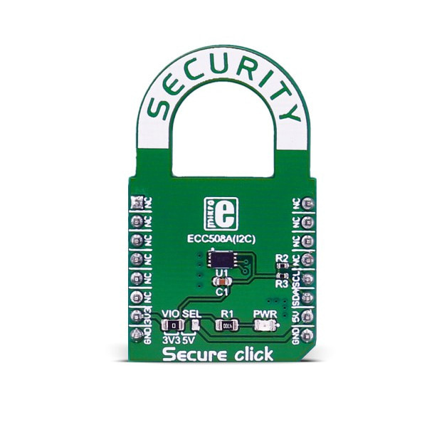
(Secure click)
개요
- 본 제품은 ATECC508A 크라입토그래픽 코프로세서 모듈입니다.
- ATECC508A는 ECDH (Elliptic Curve Diffie Hellman) 보안 프로토콜을 내장하여 매우 안전한 암호키 인코딩/디코딩 방법을 제공합니다.
- 3.3V 및 5V로 동작하며 MCU와 I2C 인터페이스로 통신합니다.
특징
-
ATECC508A features
Microchip's ATECC508A integrates ECDH (Elliptic Curve Diffie Hellman) security protocol, an ultra-secure method to provide key agreement for encryption/decryption. It also integrates the ECDSA (Elliptic Curve Digital Signature Algorithm) sign-verify authentication for the Internet of Things (IoT) market, including home automation, industrial networking, accessory and consumable authentication, medical, mobile and more.
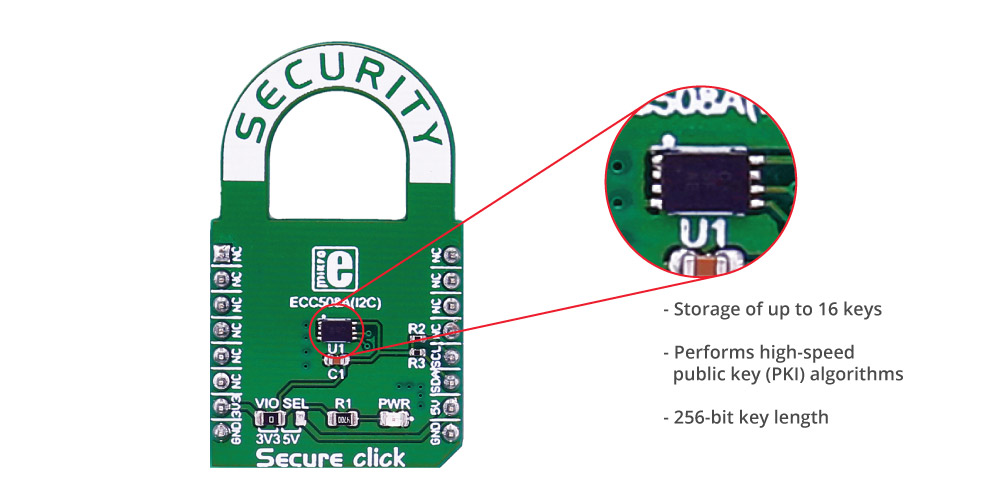
The ATECC508A includes an EEPROM array which can be used for storage of up to 16 keys, certificates, miscellaneous read/write, read-only or secret data, consumption logging, and security configurations. Access to the various sections of memory can be restricted in a variety of ways and then the configuration can be locked to prevent changes.
It features a wide array of defense mechanisms specifically designed to prevent physical attacks on the device itself, or logical attacks on the data transmitted between the device and the system. Hardware restrictions on the ways in which keys are used or generated provide further defense against certain styles of attack.Specifications
Type EEPROM Applications IoT node security and ID, secure download and boot, ecosystem control, message security, anti-cloning, etc. On-board modules ATECC508A cryptographic co-processor Key Features Performs high-speed public key (PKI) algorithms, NIST Standard P256 elliptic curve support, SHA-256 hash algorithm with HMAC option, 256-bit key length, storage for up to 16 Keys Interface I2C Input Voltage 3.3V or 5V Click board size M (42.9 x 25.4 mm) Pinout diagram
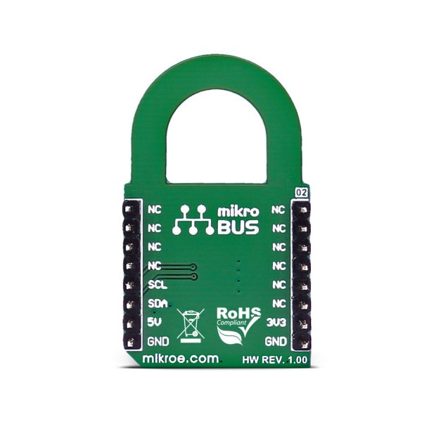
This table shows how the pinout on Secure click corresponds to the pinout on the mikroBUS™ socket (the latter shown in the two middle columns).
Notes Pin 
Pin Notes NC 1 AN PWM 16 NC NC 2 RST INT 15 NC NC 3 CS TX 14 NC NC 4 SCK RX 13 NC NC 5 MISO SCL 12 SCL I2C clock NC 6 MOSI SDA 11 SDA I2C data Power supply +3.3V 7 3.3V 5V 10 +5V Power supply Ground GND 8 GND GND 9 GND Ground Jumpers and settings
Designator Name Default Position Default Option Description JP1 PWR.SEL. Left 3.3V Power Supply Voltage Selection 3.3V/5V, left position 3.3V, right position 5V
문서
연관제품
- 연관제품 1