
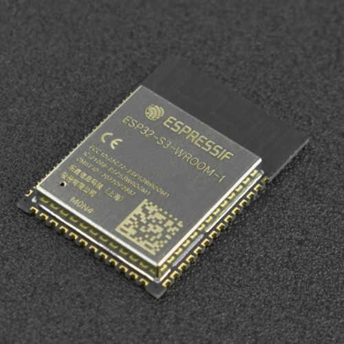
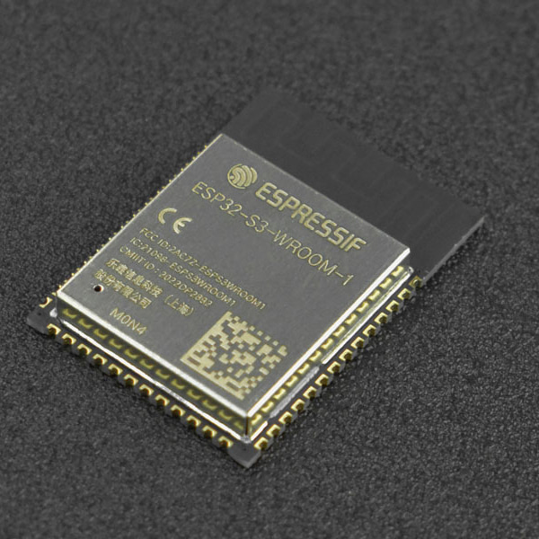
ESP32-S3-WROOM-1-N4 모듈 -PCB 안테나, 4MB 플래쉬
(ESP32-S3-WROOM-1-N4 Module (PCB Antenna))
개요
- 본 제품은 ESP32-S3-WROOM-1-N4 모듈 -PCB 안테나 입니다.
- PCB 안테나를 가지고 있는 ESP32-S3 모듈로 4MB 플래쉬를 가지고 있습니다.
특징
- ESP32-S3 series of SoCs embedded, Xtensa® dual-core 32-bit LX7 microprocessor (support single-precision floating-point units), support the clock frequency of up to 240MHz
- 384 KB ROM
- 512 KB SRAM
- 16 KB RTC SRAM
- 4 MB SPI flash
- Bluetooth LE: Bluetooth 5, Bluetooth mesh
- 40MHz crystal oscillator
- Module Dimension: 18x25.5x3.1(mm)/0.71x1.00x0.12(inches)
- Operating Temperature: –40~85℃
-
ESP32-S3-WROOM-1 is a powerful, generic Wi-Fi+ Bluetooth LE MCU module built around the ESP32-S3 series of SoCs. On top of a rich set of peripherals, the acceleration for neural network computing and signal processing workloads provided by the SoC makes the module an ideal choice for a wide variety of application scenarios related to Artificial Intelligence of Things (AIoT), such as wake word detection, speech commands recognition, face detection, and recognition, smart home, smart appliances, smart control panel, smart speaker, etc.
ESP32-S3 integrates multiple peripherals including SPI, LCD, Camera interface, UART, I2C, I2S, IR remote control, pulse counter, LED PWM, USB Serial/JTAG controller, MCPWM, SDIO host, GDMA, TWAI® controller (compatible with ISO 11898-1), ADC, touch sensor, temperature sensor, timers, and watchdogs, as well as up to 36 GPIOs. And it also includes a full-speed USB 1.1 On-The-Go (OTG) interface to enable USB communication.
")
Pinout
Pin Definitions
Name NO. Typea Function GND 1 P GND 3V3 2 P Power supply EN 3 I High level: on, enables the chip Low level: off, the chip powers off Note: Do not leave the EN pin floating IO4 4 I/O/T RTC_GPIO4, GPIO4, TOUCH4, ADC1_CH3 IO5 5 I/O/T RTC_GPIO5, GPIO5, TOUCH5, ADC1_CH4 IO6 6 I/O/T RTC_GPIO6, GPIO6, TOUCH6, ADC1_CH5 IO7 7 I/O/T RTC_GPIO7, GPIO7, TOUCH7, ADC1_CH6 IO15 8 I/O/T RTC_GPIO15, GPIO15, U0RTS, ADC2_CH4, XTAL_32K_P IO16 9 I/O/T RTC_GPIO16, GPIO16, U0CTS, ADC2_CH5, XTAL_32K_N IO17 10 I/O/T RTC_GPIO17, GPIO17, U1TXD, ADC2_CH6 IO18 11 I/O/T RTC_GPIO18, GPIO18, U1RXD, ADC2_CH7, CLK_OUT3 IO8 12 I/O/T RTC_GPIO8, GPIO8, TOUCH8, ADC1_CH7, SUBSPICS1 IO19 13 I/O/T RTC_GPIO19, GPIO19, U1RTS, ADC2_CH8, CLK_OUT2, USB_D - IO20 14 I/O/T RTC_GPIO20, GPIO20, U1CTS, ADC2_CH9, CLK_OUT1, USB_D+ IO3 15 I/O/T RTC_GPIO3, GPIO3, TOUCH3, ADC1_CH2 IO46 16 I/O/T GPIO46 IO9 17 I/O/T RTC_GPIO9, GPIO9, TOUCH9, ADC1_CH8, FSPIHD, SUBSPIHD IO10 18 I/O/T RTC_GPIO10, GPIO10, TOUCH10, ADC1_CH9, FSPICS0, FSPIIO4, SUBSPICS0 IO11 19 I/O/T RTC_GPIO11, GPIO11, TOUCH11, ADC2_CH0, FSPID, FSPIIO5, SUBSPID IO12 20 I/O/T RTC_GPIO12, GPIO12, TOUCH12, ADC2_CH1, FSPICLK, FSPIIO6, SUBSPICLK IO13 21 I/O/T RTC_GPIO13, GPIO13, TOUCH13, ADC2_CH2, FSPIQ, FSPIIO7, SUBSPIQ IO14 22 I/O/T RTC_GPIO14, GPIO14, TOUCH14, ADC2_CH3, FSPIWP, FSPIDQS, SUBSPIWP IO21 23 I/O/T RTC_GPIO21, GPIO21 IO47 24 I/O/T SPICLK_P_DIFF, GPIO47, SUBSPICLK_P_DIFF IO48 25 I/O/T SPICLK_N_DIFF, GPIO48, SUBSPICLK_N_DIFF IO45 26 I/O/T GPIO45 IO0 27 I/O/T RTC_GPIO0, GPIO0 IO35b 28 I/O/T SPIIO6, GPIO35, FSPID, SUBSPID IO36b 29 I/O/T SPIIO7, GPIO36, FSPICLK, SUBSPICLK IO37b 30 I/O/T SPIDQS, GPIO37, FSPIQ, SUBSPIQ IO38 31 I/O/T GPIO38, FSPIWP, SUBSPIWP IO39 32 I/O/T MTCK, GPIO39, CLK_OUT3, SUBSPICS1 IO40 33 I/O/T MTDO, GPIO40, CLK_OUT2 IO41 34 I/O/T MTDI, GPIO41, CLK_OUT1 IO42 35 I/O/T MTMS, GPIO42 RXD0 36 I/O/T U0RXD, GPIO44, CLK_OUT2 TXD0 37 I/O/T U0TXD, GPIO43, CLK_OUT1 IO2 38 I/O/T RTC_GPIO2, GPIO2, TOUCH2, ADC1_CH1 IO1 39 I/O/T RTC_GPIO1, GPIO1, TOUCH1, ADC1_CH0 GND 40 P GND EPAD 41 P GND - P: power supply; I: input; O: output; T: can be set to high impedance. Pin functions in bold font are the default ones. The default functions of pins 28 ~ 30 are determined by the eFuse bit.
- In modules that have embedded OSPI PSRAM (i.e., that embed ESP32-S3R8), pins IO35, IO36, and IO37 are used to connect to the OSPI PSRAM and not available for other uses.

